Learning Task 2
Install a Residential Sprinkler System
Step 4: Selecting and Locating Sprinklers
This is the point where the sprinklers are selected and plotted onto the sketch. Many would-be designers consider this to be the first step in the whole design process, but most of the criteria needed for sprinkler selection is gathered through the preliminary steps leading to this point.
The size and shape of the areas to be irrigated often determine what type of sprinkler will be used. The goal is to select the type of sprinklers that will cover the area properly using the least number of sprinklers. There are 2 basic types of sprinklers: fixed spray and rotating.
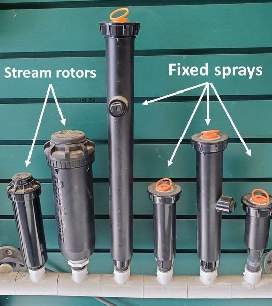
Fixed Spray Sprinklers
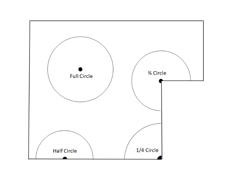
Spray sprinklers are required for smaller landscaped areas, for those areas with enclosed borders requiring tightly controlled spray, for areas with dense tree growth that would significantly hinder a rotating sprinkler’s coverage and for areas that have mixed sections of plantings that require many sprinklers because of differing amounts of water required. Spray sprinklers generally emit single or double sheets or fans of water in a fixed pattern. These patterns are usually a particular part of a circle or arc.
The most common fixed patterns are full circle, three-quarter circle (270°), two-thirds circle (240°), half circle (180°), one-third circle (120°), quarter circle (90°) and one-eighth circle (45°). In addition to the arcs, some specialty spray patterns like center strips, side strips and end strips are available that tend to spray in a rectangular pattern. Also available from some manufacturers is a variable arc nozzle which is a hybrid spray nozzle intended to handle the occasional odd-shaped, in-between area. This type of nozzle allows the designer and installer to adjust the arc of coverage from a few degrees to 360°.
Bubblers are fixed spray heads that produce short throw or zero radius water distribution. The most common type of bubbler delivers anywhere from 1/2 to 3 gpm (0.03 to 0.19 l/s), depending on the pressure available and how it is adjusted. The water either runs down the riser supporting the sprinkler, much like spillage from a container, or sprays out a few inches (centimeters) in an umbrella pattern. The advantage of a bubbler is that it can irrigate a specific area without overthrow onto other plants. Bubblers can be used in very narrow or small planting areas and can be adjusted to low flow so large numbers of bubblers can be mounted on one line.
Spray sprinklers can be either mounted on risers in shrub beds where concealment isn’t an issue or can be of a pop-up variety to avoid mowing or foot traffic interference in small lawn areas.
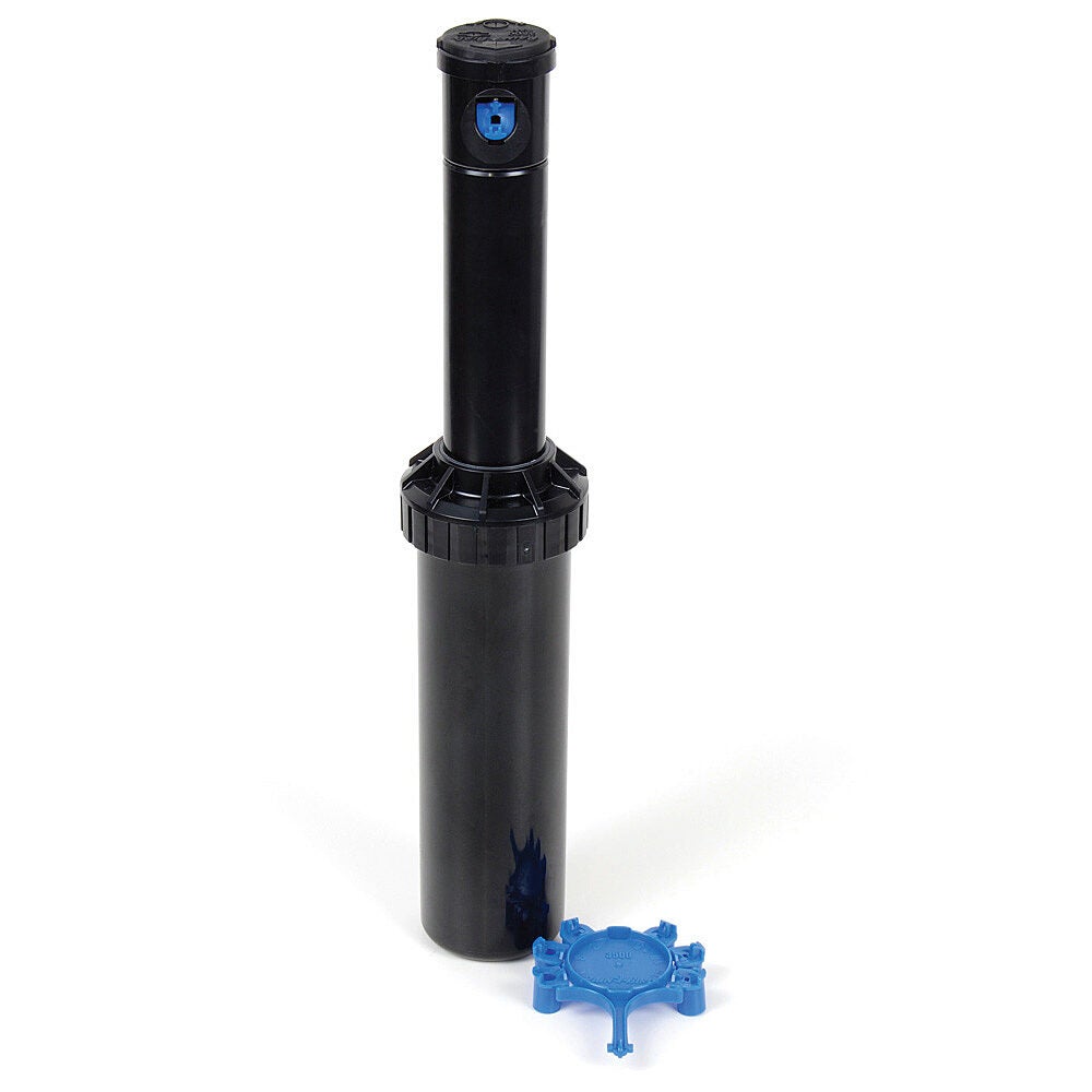
Rotating Sprinklers (Stream Rotors)
Like the spray sprinklers, rotating sprinklers are available in riser-mount configuration for irrigating larger shrub and ground cover areas, and in pop-up versions for watering turfgrasses. Rotating sprinklers use various means for converting a portion of the flow and pressure passing through them into “drive” energy to turn the sprinkler.

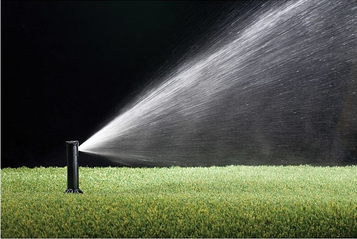
In general, rotating sprinklers have a single nozzle or pair of nozzles that revolve to distribute water over the area of coverage. Part circle units have a reversing or shutoff mechanism to avoid watering outside their arc pattern. Instead of fixed arcs of coverage, most part circle rotating sprinklers are adjustable from about 20 to 240° and many can be switched to the 360° (full circle) setting. Full-circle-only units are also available.
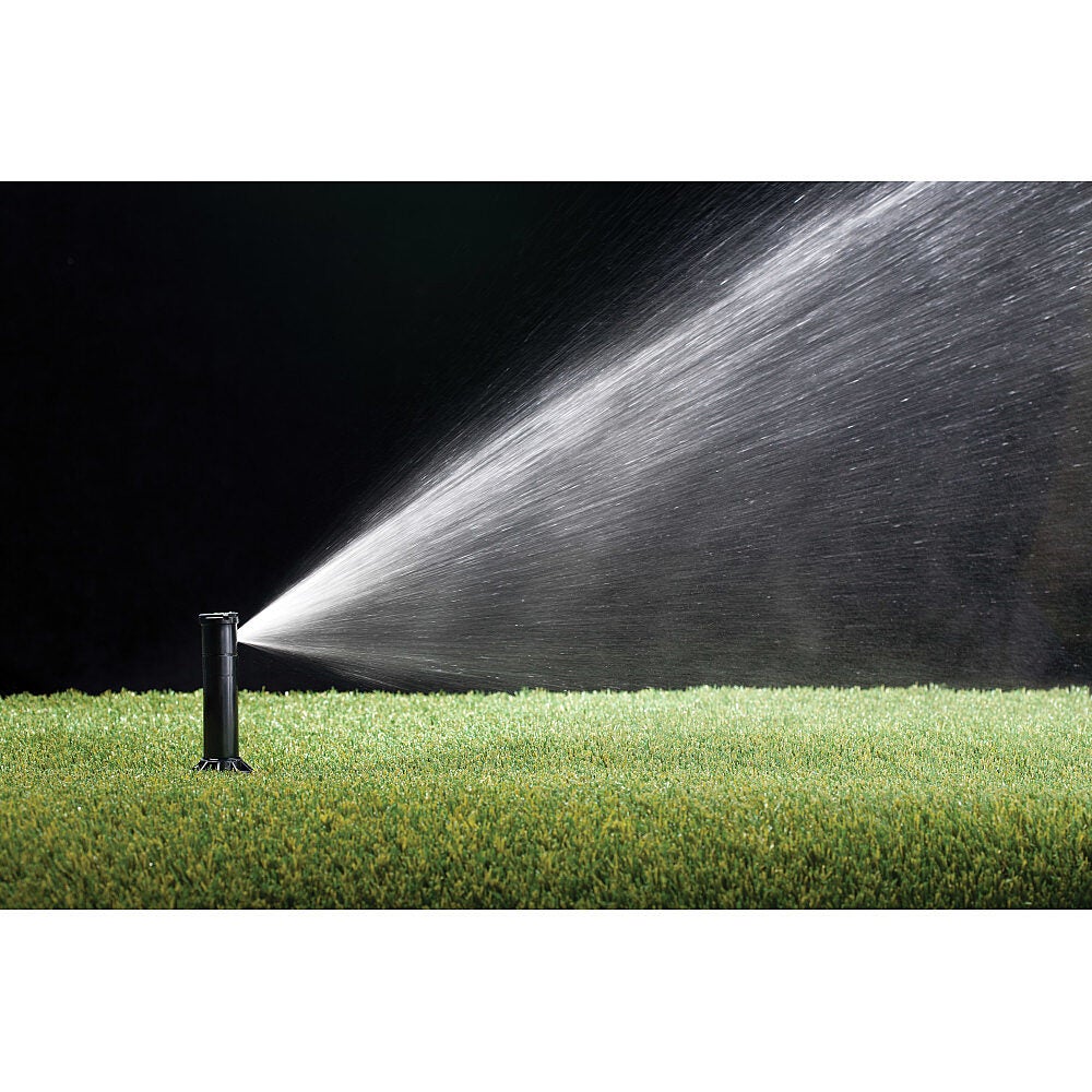
Available in a wide range of sizes, most rotating sprinklers on the market today operate somewhere in the 25 to 100 psi (175 to 700 kPa) range. The distance of throw is much greater than for spray sprinklers. Rotating sprinklers can throw from about 20 ft (6 m) minimum for the small units to well over 100 ft (30 m) of radius for larger commercial units. It should be noted that the flow demands for large radius sprinklers are much higher. Discharge rates of up to 100 gpm (6.3 L/s) are not uncommon for large rotating sprinklers used for watering golf courses, whereas flow rates of between 1 and 10 GPM are common for residential rotors.
Impact sprinklers are a variety of rotating sprinkler that are more commercial/agricultural in nature. They have a paddle that “slaps” the water stream to provide watering close to the sprinkler location as well as to cause the nozzle to move horizontally with each “slap”. Many traditional residential hose-operated sprinklers are of this variety.
Despite their large water flow, rotating sprinklers usually apply water much more slowly than spray sprinklers because the water is spread out over greater areas. The precipitation rates for these large sprinklers run more in the ¼ to 2 in/hr (6 to 51 mm/hr) range. This makes rotating sprinklers appropriate for slopes, tight soils and other areas where slower application rates are required in order to prevent runoff and erosion.
Pop-up versions of rotors and spray heads are buried deep enough so that the highest point of the sprinkler is just below the ground (not the grass) level when the system is at rest. This keeps them out of the way of mower blades and foot traffic while allowing enough height for the head to clear the surrounding grass when in operation. Pop-up valve bodies are available in lengths between 2″ and 18″ depending on manufacturer.
Economics usually drives the choice between stream rotors and fixed spray heads. The large radius sprinklers are usually more economical, and energy and water efficient for large-area irrigation, where their streams are uninterrupted and allow for full coverage. Fewer sprinklers, fewer fittings, and less trenching are definite advantages of rotating sprinklers compared to spray sprinklers, however smaller or irregularly shaped areas are usually better served with spray sprinklers.
Plotting Sprinklers
Now it is time to select and plot the sprinklers onto the drawing. Do this one area at a time. When selecting the proper sprinklers for a project, several factors should be considered. Some of these factors are:
- type of sprinklers requested by the owner
- size and shape of the areas to be watered
- types of plant material to be irrigated
- water pressure and flow available
- local environmental conditions such as wind, temperature, slope and precipitation
- soil type and the rate at which it can accept water
- compatibility of the sprinklers which can be grouped together
Tackle one area at a time. This helps to lessen the feelings of being overwhelmed by the size of any project and ensures that nothing is missed. Some points to consider when plotting sprinkler locations are:
- Start with quarter circle heads at corners, then half circle types along the borders of straight edges, full circles for large open areas and lastly specialty types for odd-shaped areas.
- Place sprinklers with the greatest radius in larger areas to reduce the numbers of sprinklers.
- Use “head-to-head” coverage; in other words, make sure the spray from one head will reach all the heads adjacent to it. This ensures uniform water application, which saves water and creates the best possible results. Nozzle specs are based on head-to-head coverage.
- Use a compass to draw the arcs to scale. This will help ensure head-to-head coverage.
- Note the GPM flow rate on the sketch beside each sprinkler. Refer to this number when assigning sprinklers to zones in Step 5.
- Avoid spraying onto buildings, fences, walls, sidewalks, driveways and streets.
- Use rotor sprinklers to cover large areas and fixed spray sprinklers for small areas.
- Do not mix fixed spray and rotors within the same zone. Rotor + rotor = OK; spray head + spray head = OK; rotor + spray head = NOT OK
- It is best to use one product manufacturer for the sprinklers, valves and controllers, to ensure they are compatible with each other.
At this stage, use the manufacturers’ nominal radius distances for the initial sprinkler spacing layout. Head-to-head coverage should be the design goal, as shown in the image below.
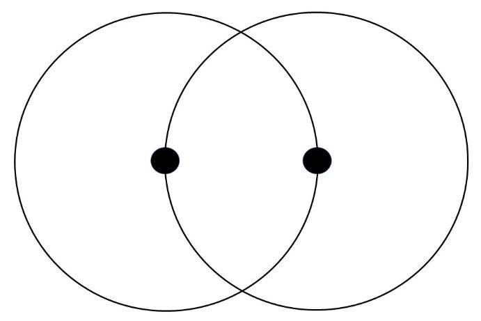
This is termed “50% spacing”, meaning that the distance between heads is 50% or half of the diameter of the spray pattern.
Spacing Patterns
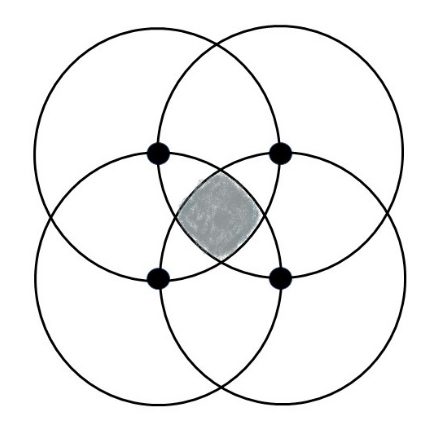
There are two main types of sprinkler spacings: square and triangular. The square pattern, with its equal sides running between four sprinkler locations, is used for irrigating areas that are square themselves, or have borders at 90° angles to each other, and that confine the design to that pattern. Although the square pattern is the weaker for proper coverage if not used carefully, enclosed areas often rule out the use of a triangular pattern. The weakness in square spacing coverage is caused by the diagonal distance between sprinklers across the pattern from each other. When the sprinklers are spaced head-to-head along the sides of the square pattern, the distance between sprinklers in opposite corners of the pattern is over 70% spacing. This 70% diagonal stretch across the square pattern can leave a “weak” spot at the center. Wind may move the weak spot slightly away from the center and summer heat may make the weak spot quite large if it is a common climatic condition for the site. If windy conditions are common, it may be prudent to reduce the spacing between heads to 45 or even 40%. This will increase the number of heads required.
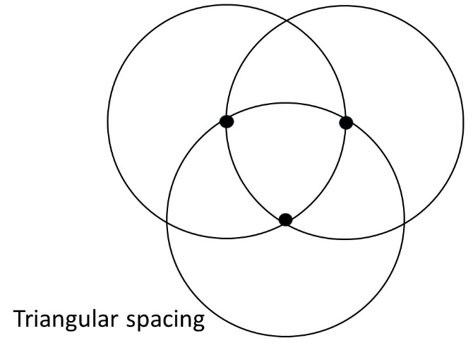
A better choice of spacing is triangular. This pattern is generally used where the area to be irrigated has irregular boundaries or borders that are open to over spray, or do not require part-circle sprinklers. The equilateral triangle pattern, where the sprinklers are spaced at equal distances from each other, has a distinct advantage over square spacing. Because the rows of sprinklers are offset from adjacent rows to establish the triangular pattern, the weak spot that could be a problem in square spacing is absent. In most cases, the sprinklers can be spaced further apart, possibly to 60% of their diameter depending on wind conditions. This additional distance between sprinklers often means fewer sprinklers will be required on the project. This translates to less equipment cost for the project, less installation time and lower maintenance costs over the life of the system.
The determination of run times for the zone valves will be dependant upon precipitation rates from the heads and those will be dependant upon whether the spacings are square or triangular.
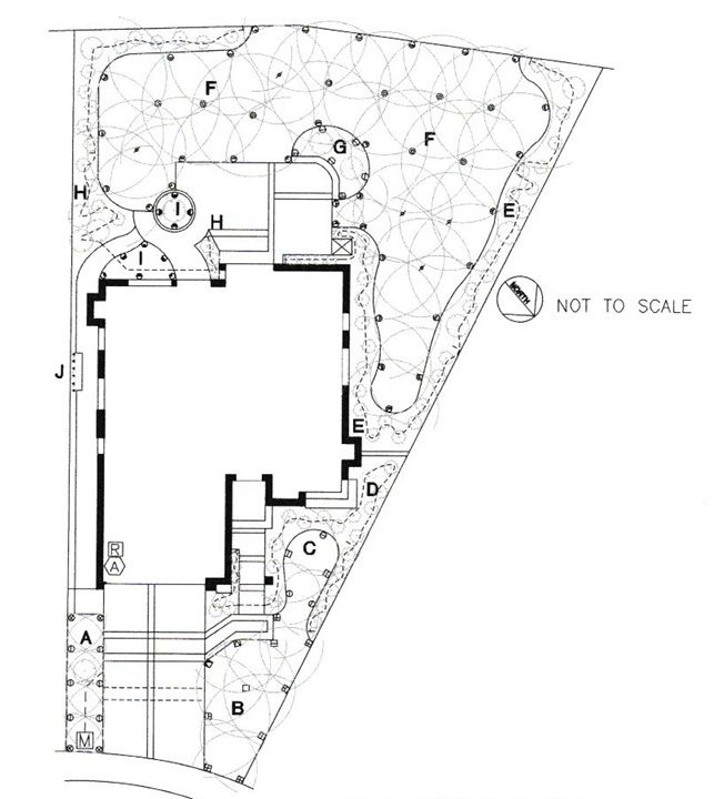
Once sprinklers are initially plotted, a site plan might look like the one below.
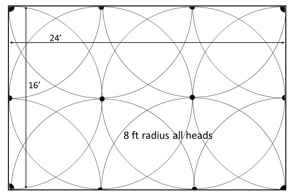
Most sprinklers have interchangeable nozzles with differing radii, trajectory angles, spray patterns and flow rates. The distance that a nozzle “throws” water is referred to as its radius. The farther the radius, the higher the flow rate in GPM. For each sprinkler location, choose a nozzle with a radius that keeps the spray pattern within the area being watered. For instance, if a rectangular area is 24′ (7.2m) x 16′ (4.8m), using sprinklers with an 8′ (2.4m) radius would provide equal spacing and head-to-head coverage in a square pattern between all sprinklers.
5′ (1.5m), 8′ (2.4m), 10′ (3m), 12′ (3.6m) and 15′ (4.5m) are common radii of nozzles for fixed spray heads. Stream rotors for residential use are capable of radii from 20 to 25 feet (6 to 10.5 m).
The actual radius of a nozzle is affected by the pressure at the head. For example, a certain manufacturer’s spray nozzle listed as “12′ Series” has a radius of 11′ @ 20 psi, 12′ @ 30 psi and 13′ @ 40-50 psi. The precipitation rates and GPM will also increase with the increase in radius. This is illustrated in the table of nozzle data below.
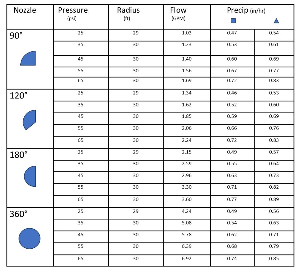
The designer can circle back to this stage of planning when assigning sprinklers to zones in a later step. Nozzle selection can be tweaked to ensure that the flow rate of the zone doesn’t exceed the supply capability while still ensuring adequate coverage. It is important to note that sprinklers should be supplied with at least the pressure needed for correct radius of throw, but no higher pressure than the manufacturer suggests. Too much pressure at a head produces a mist rather than a stream of droplets. Mists will easily be carried away by the slightest gust of wind and not reach the intended target. Most design work assumes an operating pressure of between 25 and 65 psi (172 and 448 kPa).
Step 5: Layout of Zone Valves and Main Lines
Now it is time to divide your sprinklers into groups, called zones. A zone is simply a group of sprinkler heads connected with pipe fed by a single valve. Each zone valve is controlled by the system’s controller/timer. The basic idea is to group together areas of the property that have the same watering needs, so the sprinkler heads supplying each area will water on the same schedule. In this way, you can tailor the watering needs of the different areas of plants. The idea is to divide similar sprinklers into groups such as lawn areas, shrub areas, shady areas and sunny areas.
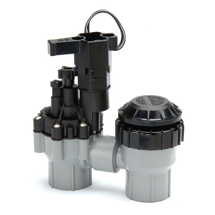
There are two types of zone valves: anti-siphon and in-line. Before selecting either, check your local codes to determine which is appropriate in your area.
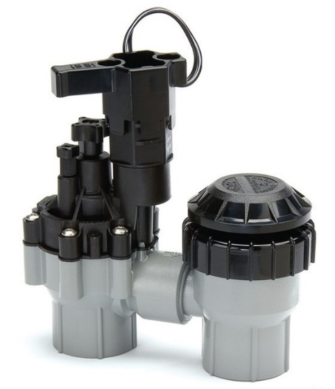
Anti-siphon zone valves have backflow prevention devices integrated into each individual valve to keep the water from the sprinkler system (and any contaminates that water could carry) from entering the clean potable water supply through backflow. The main disadvantage to the use of anti-siphon valves is that they must be installed above ground, 6” to 12” above the highest sprinkler or according to local codes. This may interfere with vehicle/foot traffic and is likely also to be an aesthetic issue. However, installing anti-siphon valves at every zone valve location negates the need for a single backflow preventer at the source of supply. Again, check with the local AHJ as well as the property owner to see if this is a viable option before designing the system.
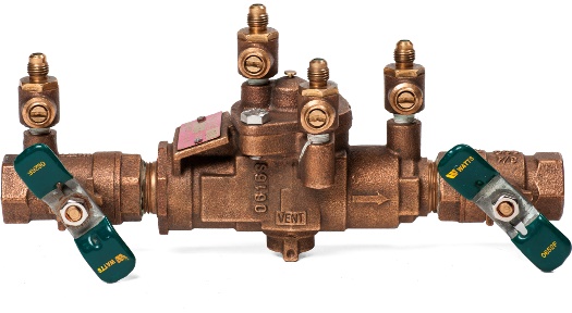
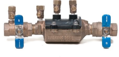
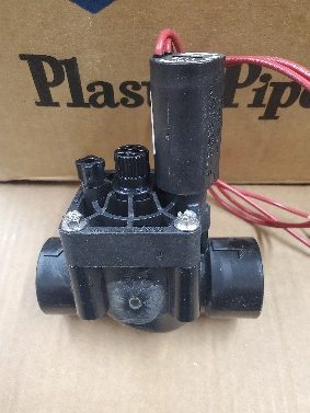
In-line valves are most common and are installed below ground in valve boxes for out-of-sight operation. However, when using in-line valves, the system will need to be protected from backflow by the installation of an approved backflow preventer. A reduced pressure backflow assembly (RPBA) or a double check valve assembly (DCVA) is normally specified by the AHJ to be installed at the point where the irrigation system connects to the potable water piping.
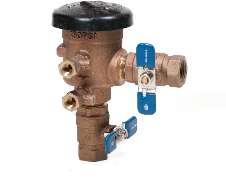
Alternatively, a pressure vacuum breaker assembly (PVBA) can be used in place of an RPBA or DCVA to protect the entire system from back siphonage backflow, provided it is installed and located appropriately.
All three devices mentioned above are “in-line testable”, meaning they can be checked for correct operation without being removed from the piping. Annual testing of RPBAs, DCVAs and PVBs is a normal requirement for irrigation systems.
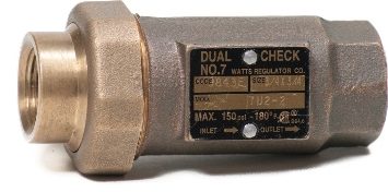
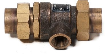
Some jurisdictions allow the use of a dual check valve (DCV) or a dual check with atmospheric port (DCAP) for system protection. These devices are not in-line testable and should not be used if a testable backflow preventer is required.
Residential anti-siphon and in-line zone valves are a normally closed (NC) electrically operated globe-type valve that will open when supplied with 24VAC from the timer. They can also be opened manually if needed. Many zone valves contain a flow control feature that can throttle the water volume being supplied to the sprinklers to further fine-tune the water distribution.
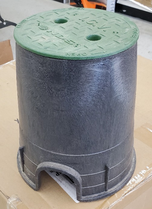
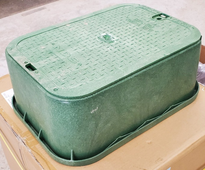
Zone valves are usually located below ground in irrigation boxes. The boxes are available in different shapes and dimensions and are specifically designed to easily allow piping and zone valve installation within them while blending in with their surroundings. They are made of PVC or ABS plastic and have lockable lids that will withstand normal foot and light mower traffic.
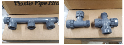
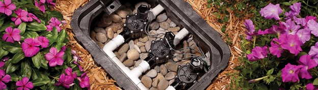
The idea behind locating zone valves is to try to group or consolidate them together into manifolds near to the sprinklers being served. Manifold fittings are available that allow two or more zone valves to be piped together in a compact fashion.
The manifold locations are entirely a matter of choice. Try to place them in areas where they won’t interfere with pavement or concrete. Flower beds near the house are common locations for them.
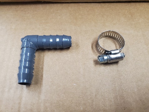
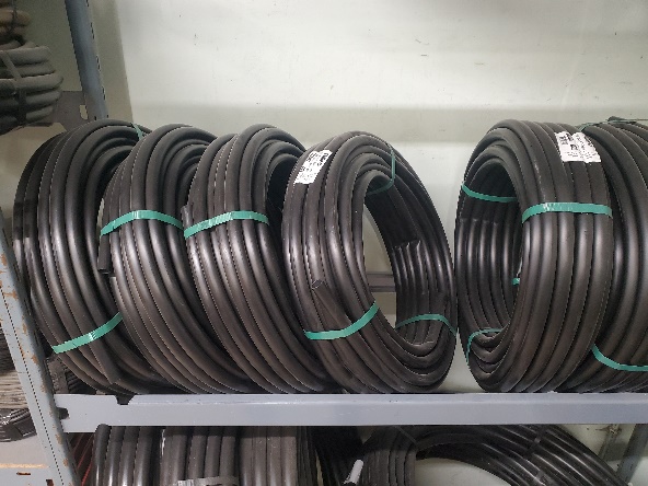
Main lines run from the point of connection of the water supply to the zone valve boxes and should be installed as directly as possible between these two points. This will minimize pressure loss through excessive numbers of fittings. For residential irrigation these lines will normally be ¾″ or 1″ PVC Schedule 40 pipe. Class 200 PVC pipe is also popular for use in irrigation systems but is normally limited to use between the zone valves and sprinklers due to its thinner walls and lower burst strength. Polyethylene (PE) pipe is also an option. It comes in coils of up to 1000 feet (300m) and is connected using barbed fittings and gear clamps. There is more pressure drop through this type of piping due to the type of fittings being used, thus restricting flow. Also, the pipe is more difficult to install in a straight trench due to its tendency to recoil itself. However, this system requires less installation tools, fittings and associated knowledge than does a PVC system. 90-degree elbows aren’t normally required because the pipe can be bent into a tight radius and trenches therefore can run directly between two points without needing to be straight and parallel. It is commonly installed by homeowners of small systems.
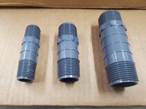
Any threaded nipples used will be SCH 80 due to the wall thickness needed in order to be threaded.
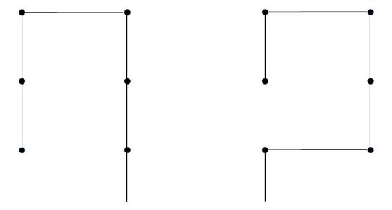
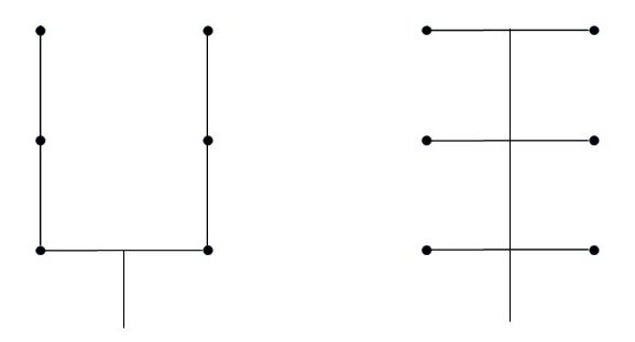
Each sprinklered area will need at least one zone valve. The number needed will depend on the available GPM as determined in Step 3 and the flow rate of the sprinklers in the area being watered from Step 4. For instance, if the available flow rate at 40 PSI was 7 GPM, and flow rate for all the sprinklers in a particular area totalled 16 GPM, then the sprinklers would need to be split between 3 zone valves unless nozzles can be changed resulting in lower flow rates. The piping would be run from the valves to the heads in as direct a line as possible and in a balanced manner. The diagrams below show a couple of examples of correct versus incorrect feed patterns to multiple heads.
Step 6: Sizing Pipe and Valves and Calculating Total System Pressure Loss
Sizing Pipe
Many designers of average-sized residential systems will use rule-of-thumb methods, such as using 1″ pipe to feed the valve manifolds and ¾″ pipe to supply stream rotors, with ½″ pipe to any fixed spray sprinkler from a ¾″ branch line. While this method may work in most cases, there are times when a more accurate method is needed to ensure the system isn’t undersized. Designing PVC piping systems to keep water flows rates no higher than 5 ft/sec (1.5m/sec) is the accepted standard. This keeps pressure losses due to friction to a minimum which ensures adequate pressure to all the sprinklers and minimizes erosion due to excessive velocities. The two charts below are generic industry standards for Sch 40 and Class 200 PVC pipe. They list flow rates from 1 to 12 GPM which are typical for most residential installations. They also show pipe sizes from ¾″ to 1 ¼″ which are also typical for those installations.
| SIZE | ¾ IN | 1 IN | 1¼ IN | |||
|---|---|---|---|---|---|---|
| flow gpm | velocity fps | psi loss | velocity fps | psi loss | velocity fps | psi loss |
| 1 | 0.47 | 0.06 | 0.28 | 0.02 | 0.18 | 0.01 |
| 2 | 0.94 | 0.22 | 0.57 | 0.07 | 0.36 | 0.02 |
| 3 | 1.42 | 0.46 | 0.86 | 0.14 | 0.54 | 0.04 |
| 4 | 1.89 | 0.79 | 1.15 | 0.24 | 0.72 | 0.08 |
| 5 | 2.36 | 1.20 | 1.44 | 0.36 | 0.90 | 0.12 |
| 6 | 2.83 | 1.68 | 1.73 | 0.51 | 1.08 | 0.16 |
| 7 | 3.30 | 2.23 | 2.02 | 0.67 | 1.26 | 0.22 |
| 8 | 3.77 | 2.85 | 2.30 | 0.86 | 1.44 | 0.28 |
| 9 | 4.25 | 3.55 | 2.59 | 1.07 | 1.62 | 0.34 |
| 10 | 4.72 | 4.31 | 2.88 | 1.30 | 1.80 | 0.42 |
| 11 | 5.19 | 5.15 | 3.17 | 1.56 | 1.98 | 0.50 |
| 12 | 5.66 | 6.05 | 3.46 | 1.83 | 2.17 | 0.59 |
| SIZE | ¾ IN | 1 IN | 1¼ IN | |||
|---|---|---|---|---|---|---|
| flow gpm | velocity fps | psi loss | velocity fps | psi loss | velocity fps | psi loss |
| 1 | 0.60 | 0.11 | 0.37 | 0.03 | 0.21 | 0.01 |
| 2 | 1.20 | 0.39 | 0.74 | 0.12 | 0.42 | 0.03 |
| 3 | 1.80 | 0.84 | 1.11 | 0.26 | 0.64 | 0.07 |
| 4 | 2.40 | 1.42 | 1.48 | 0.44 | 0.85 | 0.12 |
| 5 | 3.00 | 2.15 | 1.85 | 0.66 | 1.07 | 0.18 |
| 6 | 3.60 | 3.02 | 2.22 | 0.93 | 1.28 | 0.25 |
| 7 | 4.20 | 4.01 | 2.59 | 1.24 | 1.49 | 0.33 |
| 8 | 4.80 | 5.14 | 2.96 | 1.59 | 1.71 | 0.42 |
| 9 | 5.40 | 6.39 | 3.33 | 1.97 | 1.92 | 0.52 |
| 10 | 6.00 | 7.77 | 3.70 | 2.40 | 2.14 | 0.63 |
| 11 | 6.60 | 9.27 | 4.07 | 2.86 | 2.35 | 0.75 |
| 12 | 7.21 | 10.89 | 4.44 | 3.36 | 2.57 | 0.89 |
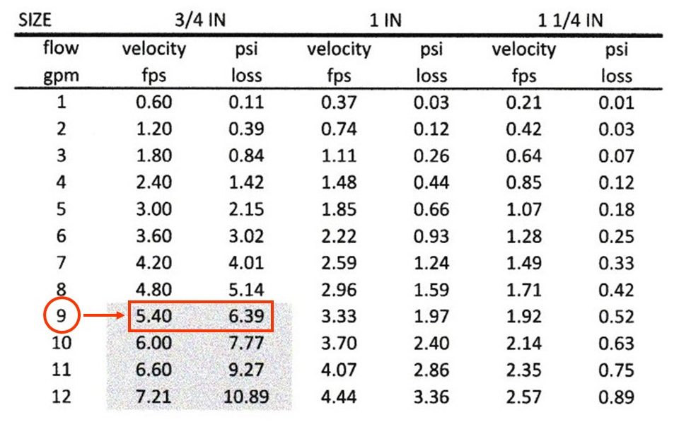
The tables are based on 100 feet (30m) of pipe. Using a size of pipe at a flow rate that lands within the shaded areas of the chart should be avoided. For example, trying to supply 9 GPM through a ¾″ SCH 40 pipe would incur a friction loss of 6.39 psi (44 kPa) for every 100 ft (30m) of pipe, and this would also operate at over 5 ft/sec (1.5m/sec) velocity as shown in the table below.
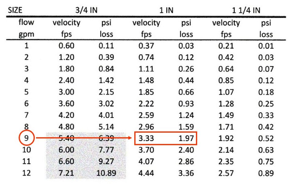
A better choice for a 9 GPM flow rate would be to use 1″ SCH 40 pipe at a velocity of 3.33 ft/sec (1m/sec) and a friction loss of only 1.97 psi (13.6 kPa) per 100 ft (30m), as seen below.
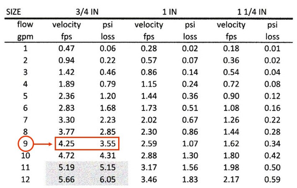
Because of the difference in wall thickness, Class 200 will allow more flow at lower friction loss than will the same size of SCH 40 pipe. Using ¾″ Class 200 for a 9 GPM flow rate would also keep velocity and pressure loss within acceptable limits (see below).
Therefore, keeping flow rates from exceeding 5 ft/sec (1.5m/sec) keeps pressure losses to acceptable limits. This assumes that most residential pipe runs won’t have much more than 200 ft (60m) of pipe in any one zone supplied with pressures in the range of 50 – 60 psi (345 – 415 kPa). The charts above are for straight runs of 100 feet of pipe. An industry standard is to add another 25% to the measured length to allow for fittings, like methods used when calculating losses through hydronic heating systems.
One well known supplier/manufacturer of sprinkler components suggests these flow limits for PVC pipe:
- ¾″ SCH 40 = 8 GPM
- 1″ SCH 40 = 13 GPM
- ¾″ Class 200 = 10 GPM
- 1” Class 200 = 15 GPM
As you can see, due to its greater internal area, Class 200 pipe allows slightly more flow than SCH 40.
Depending on local codes and zone GPM, consider using 1″ Schedule 40 PVC pipe upstream of control valves and at least ¾” Class 200 PVC pipe or ¾″ poly pipe downstream. Remember that the piping upstream of a zone valve will always be pressurized and SCH 40, because of its higher burst strength, may be the better choice than Class 200 for that location. Piping downstream of a zone valve is only subjected to dynamic pressure and can therefore be either Class 200 PVC or polyethylene pipe with a lower burst strength.
Zone Valves
Sizing zone valves for residential use is fairly straightforward. Residential valves have plastic bodies with either ¾″ or 1” slip-fit (glued) or MIP threads at their inlets and outlets. In general, use the same size valve as the pipe it will be attached to. Bodies larger than 1” are readily available if needed. While using a valve that is one size smaller than the piping is an acceptable practice, never reduce to two sizes smaller.
Calculating Pressure Losses
Pressure losses will be influenced by the type and size of pipe being used, the flow rate and the length of the piping. Once sprinklers are plotted on the site plan and their flow rates are written in adjacent to them, they are grouped together into zones so that the sums of the flows to each sprinkler stay within the general flow rate limits for the desired size of pipe listed above. Once this is done, to more accurately check the pressure losses on each zone, measure the distance from the source of supply through the zone valve to the furthest sprinkler and add 25% to compensate for fittings. Divide this number by 100 to come up with a multiplier for the length that will be used in a subsequent step. Then, using the friction loss table for the specific pipe being used, enter the table at a flow rate in GPM that is equal to or just above the actual flow to all the heads in that zone. Read across to the column for the size of pipe being used and note the number in the column for pressure loss in PSI. Multiply that number by the multiplier arrived at above. This will be the pressure loss in PSI for that zone. Then subtract that number from the pressure available to the zone. What this leaves you with is the pressure available to operate the sprinklers in that zone. Remember that, in general, a sprinkler should have at least 35 psi (241 kPa) for proper operation but always consult the manufacturer to see what their minimum operating pressure is. If what you are left with is less than what is needed, re-configure the zone piping to shorten it if possible, or remove a sprinkler to decrease the total flow rate and re-organize the zones. To not consider the pressure losses when sizing may lead to having zones operate where the water isn’t being thrown to the distances that were planned. This may result in having areas that aren’t being given enough water and plant die-off is likely.
Now complete Self Test 2 and check your answers. Answers are at the end of this learning guide.
Self-Test 2
Self-Test 2
- What type of sprinkler nozzle has almost no spray radius?
- 90° part circle
- Stream rotor
- Variable arc
- Bubbler
- What type of sprinkler is best suited for small areas that may require many heads?
- Stream rotor
- Fixed spray
- Bubbler
- Impact
- What type of sprinkler is used in areas where there may be conflict with foot or vehicular traffic?
- Pop-up
- Impact
- Full circle
- Variable arc
- What type of sprinkler has a paddle that “slaps” the water stream to cause the head to rotate?
- Stream rotor
- Fixed spray
- Impact
- Pop-up
- What type of sprinkler is best for slopes and tight soils where lower precipitation rates are preferred?
- Pop-up
- Rotating
- Part circle
- Fixed spray
- Which one of the following choices would not be an advantage of a rotating sprinkler over a spray sprinkler?
- Fewer fittings
- Less trenching
- Fewer sprinklers
- Ability to serve small areas
- When plotting sprinklers on the site plan, what design aspect saves water and ensures its uniform application?
- Use head-to-head coverage
- Use spray heads for large open areas
- Use stream rotors for small, confined spaces
- Mix stream rotors and fixed spray heads on the same zone
- Which component of a sprinkler system has its own backflow preventer built into it?
- A stream rotor
- A fixed spray head
- An inline zone valve
- An anti-siphon zone valve
- Which two backflow preventers are normally specified by AHJs for installation on irrigation systems because of their ability to be in-line tested?
- RPBAs and DCVAs
- DCAPs and RPBAs
- DCVs and DCAPs
- DCVs and DCVAs
- Which one of the following is not an in-line testable backflow preventer?
- DCVA
- DCAP
- RPBA
- PVBA
- Which one of the following is likely not a good location for a zone manifold?
- In a planter
- In a driveway
- In a flower bed
- In the lawn near the water supply
- Which one of the following acceptable irrigation pipes has the most pressure drop, fewest fittings and requires the least amount of trade knowledge to install but is most difficult to keep in alignment?
- Polyethylene (PE)
- Class 200 PVC
- SCH 40 PVC
- SCH 80 PVC
- What factors determine the number of zone valves needed?
- Owner’s wishes and site geography
- Wind speed expected and local rainfall
- Available GPM and sprinkler flow rates
- Power supply available and house pressure
- Which one of the following zone layouts would be most likely to cause the most even pressure at the heads?
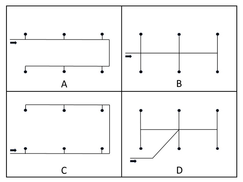
- A
- B
- C
- D
- According to most pipe manufacturers, what is the industry-standard maximum velocity for PVC pipe used for irrigation systems so that friction loss is kept to a minimum?
- 5 ft/sec (1.5 m/sec)
- 8 ft/sec (2.4 m/sec)
- 10 ft/sec (3.0 m/sec)
- 15 ft/sec (4.5 m/sec)
- Using the tables in the text, what would be the friction loss for 100 feet of ¾” SCH 40 PVC pipe if the flow rate was to be 5 GPM?
- 0.66 psi
- 2.15 psi
- 3.44 psi
- 8.46 psi
- Why does Class 200 PVC allow more flow than SCH 40 PVC?
- Because of its higher burst strength
- Because it has better UV resistance
- Because of its wall thickness difference
- Because in the difference in its chemical makeup
- According to industry standards, how much extra length should be added to the measured length to allow for friction loss through fittings in an irrigation system?
- 10%
- 25%
- 40%
- 50%
- What is the body size of most residential irrigation zone valves?
- ½″ and ¾″
- ¾″ and 1″
- 1″ and 1 ¼″
- 1 ¼″ and 1 ½″
- According to information in the preceding text, what is one manufacturer’s “rule-of-thumb” flow rate for 1” PVC SCH 40 pipe?
- 8 GPM
- 10 GPM
- 13 GPM
- 15 GPM
Check your answers using the Self-Test Answer Keys in Appendix 1.
Media Attributions
- Figure 1 Stream rotors and fixed spray heads by ITA is licensed under a CC BY-NC-SA licence.
- Figure 2 Examples of Fixed Spray Patterns by ITA is licensed under a CC BY-NC-SA licence.
- Figure 3 Rainbird® 3500 stream rotor with nozzle assortment © Irrigation Direct Canada. Used with permission.
- Figure 4 Rainbird® 3500 pop-up stream rotor in operation © Irrigation Direct Canada. Used with permission.
- Figure 5 Head-to-head coverage by ITA is licensed under a CC BY-NC-SA licence.
- Figure 6 Weak spot caused by square spacing by ITA is licensed under a CC BY-NC-SA licence.
- Figure 7 Triangular spacing by ITA is licensed under a CC BY-NC-SA licence.
- Figure 8 Example of a site plan after plotting sprinklers is adapted from image © Irrigation Direct Canada. Used with permission.
- Figure 9 Using spray heads with 8 foot radii by ITA is licensed under a CC BY-NC-SA licence.
- Figure 10 Example of nozzle data by ITA is licensed under a CC BY-NC-SA licence.
- Figure 11 RPBA by Camosun College is licensed under a CC BY 4.0 licence.
- Figure 12 DCVA by Camosun College is licensed under a CC BY 4.0 licence.
- Figure 13 PVBA by Camosun College is licensed under a CC BY 4.0 licence.
- Figure 14 DCV by Camosun College is licensed under a CC BY 4.0 licence.
- Figure 15 DCAP Camosun College is licensed under a CC BY 4.0 licence.
- Figure 16 Anti-siphon zone valve © Irrigation Direct Canada. Used with permission.
- Figure 17 In-line zone valve by Okanagan College is licensed under a CC BY-NC-SA licence.
- Figure 18 Round irrigation box by Okanagan College is licensed under a CC BY-NC-SA licence.
- Figure 19 Rectangular irrigation box by Okanagan College is licensed under a CC BY-NC-SA licence.
- Figure 20 Manifold fittings by Okanagan College is licensed under a CC BY-NC-SA licence.
- Figure 21 Manifolded zone valves in irrigation box © Irrigation Direct Canada. Used with permission.
- Figure 22 Barbed fitting and gear clamp for PE systems by Okanagan College is licensed under a CC BY-NC-SA licence.
- Figure 23 Polyethylene (PE) pipe by Okanagan College is licensed under a CC BY-NC-SA licence.
- Figure 24 SCH 80 PVC nipples by Okanagan College is licensed under a CC BY-NC-SA licence.
- Figure 25 Incorrect zone piping configurations by Okanagan College is licensed under a CC BY-NC-SA licence.
- Figure 26 Incorrect zone piping configurations by Okanagan College is licensed under a CC BY-NC-SA licence.
