Learning Task 3
Installation and Wiring of Controllers
Step 7: Locating Controllers and Sizing Wire
Once the number of zones needed is finalized, choose a controller that can operate at least that number of zones. A good option is to also allow for an extra zone or two for future alterations to the landscaping.
Controllers should be located close to a 120VAC wall plug. On a wall inside a garage is a common location as it is protected from the weather, however it may be difficult to observe the zones in operation from this location. If mounted on an outside wall near a weatherproof plug, it should be certified for outdoor installation and, as such, will need to be housed inside a weatherproof cabinet. This will undoubtedly incur extra cost but will prove advantageous for viewing system operation during initial setup or for routine maintenance. Remember that “weatherproof” doesn’t necessarily imply that it is waterproof so make sure it is protected from direct rain or snow and any spray from the system.
Wires must be run from the controller to each zone valve. The zone valves will have two wires, one of which will be a power lead (“hot” wire) and one that is a “common” or “ground” wire. Each zone in the controller is numbered and will have one hot wire terminal per zone. There will be a single common terminal on the controller that all the common wires will connect to.
Individual wires are insulated and contained within cables of 3 to 13 conductors. Any cables used must be acceptable for “direct earth burial”. Wholesalers and retailers of irrigation products will carry the correct type of cables for underground installation. Cables are run between the manifolds and the controller. They should have one hot wire per zone valve and one wire for all the zone valve grounds to gather and attach to. As well, it is a good idea to have at least one extra hot wire at any manifold location to accommodate an extra future zone.
The cables are run within the same trench as the main line to the manifold, often taped or strapped to the main pipe and tucked underneath it to lessen the chances of contact with shovels during the backfilling process. The most common size of wire for residential systems is 18-gauge (#18AWG). This gauge is more than heavy enough to carry 24 VAC from the controller to the zone valve location, considering that the zone manifolds are not usually very far from the supply water main. If excessive length to the manifold is anticipated, consult an electrician or wire manufacturer and have the voltage and amperage ratings of the controller, transformer and zone valve handy for reference.
Step 8: Installing the System
Once the system is designed and checked for conformance to codes and bylaws, make sure the piping routes between the water supply and manifolds and between the manifolds and sprinklers are drawn onto the plan. Multiple pipes can share trenches to minimize digging.
Make sure to use proper Personal Protective Equipment (PPE) that are CSA-approved and appropriate for the work before starting.
Mark the sprinkler locations on the site using small flags on wire stems. These are available through any of the equipment suppliers. This makes the sprinkler locations easy to spot and will help when laying out the trenching to them. Also, mark the location of any drip system risers. Although not discussed here, if you plan to install a drip system later, you can install any piping to drip risers in the trenches with the rest of your system. Next, determine the location of the valve manifold boxes. Use line-marking spray paint to mark the approximate size of the boxes and then mark the trenches between the water supply, manifolds and sprinklers. Do this as accurately as possible. You will be digging your trenches along these lines.
The trenches need not be too deep, usually between 8 inches (200 mm) and 12 inches (300 mm). Most installers will use the depth of the shovel’s nose as a guide. If the piping connection at a sprinkler is below this level, the use of a swing joint at the head will accommodate the difference in elevations. An installer may choose to use a power trencher if there is a lot of trenching to do or moderately rocky ground is expected. Even the smallest machine is capable of depths up to 24 inches (600 mm). If trenching through existing lawn, use a square-nosed shovel to remove rectangular pieces of sod of approximately 2 inches (50 mm) thick. Lay heavy plastic film on each side of the trench. Place the sod on one side and spoils on the other. This makes it much easier to backfill and replace the sod in a way that minimizes unwanted excess soil left on the lawn and looks professional. Slightly mound the trench backfill to allow for settlement.
If trenching under a sidewalk is necessary, create a “pipe jetter” by taking a pipe of PVC pipe about 1 foot (300 mm) longer than the width of the sidewalk and gluing a hose adapter onto one end. On the other end, glue on a jet nozzle that is available through irrigation suppliers or make one from a PVC cap by drilling a few small holes in it. Dig out an entry and an exit point on either side of the sidewalk, attach a hose to the end of the jetter and turn on the water. You should be able to push and wiggle the assembly under the concrete without too much effort. Once through, cut off each end and couple the lateral line to it. Use a larger pipe for jetting to create a sleeve if two or more lines or control wires are needed to be run under the sidewalk.
Dig the hole at the manifold box location(s). It should be deep enough to allow the placing of approximately 6 to 12 inches (150 to 300 mm) of drain rock in the bottom. This helps drain the box and keeps it from becoming muddy.
Dig a hole at all sprinkler locations to allow the head to be attached to the pipe via a swing joint. Swing joints allow 3-directional movement for easier sprinkler placement as well as allowing some vertical movement in case the sprinkler encounters vehicular traffic on it. Swing joints can be either threaded PVC nipples and fittings or can be flexible high-strength composite pipe that uses friction-fit barbed-to-threaded fittings, as shown in the image below.
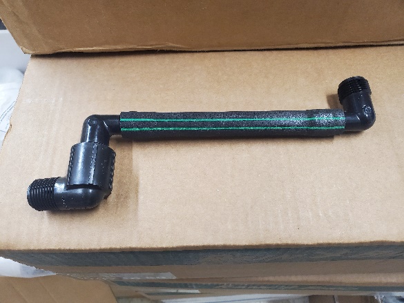
Most manufacturers have their own variety of this pipe. Toro® calls theirs “Funny Pipe” and suggests a length of “Funny pipe” of between 1 foot (300 mm) and 4 feet. Tees used on the laterals feeding the swing joints are available as SL × SL × FIP (slip × slip × female thread). Use Teflon® tape on all threaded joints except the base of the sprinkler; these are to be left bare.
Once the excavating is completed, lay out the piping on the ground beside the trenches. Pipes can be cut to length and assembled above grade before being placed into the trench. This makes the job easier and can help keep unwanted debris out of the pipe. Use the correct primers and glues for the material chosen. Connect all piping except the swing joints and sprinklers. This is done after flushing.
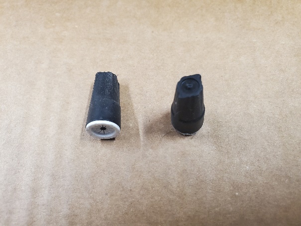
Connect the wiring at the zone valves and at the controller. Wire insulation is coloured so take note of the colour of the hot wire connected to each zone valve, assign each valve a number and connect the wires to the corresponding terminals at the timer. Remember that the common zone valve wires are connected in the valve box to a common wire in the cable and that wire connects to the common terminal on the controller. Wire connections made underground are done by using a waterproof twist-on connector, similar to a “Marrette”® as shown below. The bared wire ends are twisted together first, then the connector is threaded onto the twisted wires.
Step 9: Flushing, Testing and Commissioning
Flushing and Testing the Supply Main to Zone Valves
While the glued joints are curing, backfill all the trenches leaving the space open around any joint. Make sure all system valves are manually closed and electrically deenergized. Disconnect the inlets to the zone valves if unions were used; if not, leave the pipe connected, as any debris in the zone valve may either pass through into the sprinkler laterals and be flushed through or can be removed from the valve by taking off its bonnet and flushing it. Once all the glued joints are sufficiently cured (see pipe manufacturer’s literature), open the water source supply valve and flush the mains to the zone valves, then close the supply valve, reconnect the inlets to the zone valves and reopen the supply valve to pressurize the mains feeding the zone valves. Walk the mains’ routes to ensure there are no leaks.
NOTE: When opening valves, do it slowly to avoid creating water hammer.
Flushing the Zone Piping
Install all but the furthest head on a pipe run. This will allow dirt or debris to be pushed out the open end. Open the zone valve and flush until the water exiting the opening runs clear. Shut the valve and install the last sprinkler. Repeat this procedure for each zone. Pressure testing is not normally performed on zone piping; this is the reason that the pipe joints are left uncovered up to this point.
Operate the Timer to Cycle the Zones
Most controllers will have a setting for opening each zone, one at a time, for testing purposes. Each zone will stay energized for a short time, usually 2 minutes. Use this setting to operate each zone and walk the piping to check for leaks. Then, with all zones off, the entire system can be backfilled, and sprinklers can be set at their final desired height. To then set each sprinkler to its final intended arc, open its zone valve either manually or electrically. Consult the manufacturers’ literature for instructions on sprinkler arc adjustments as they can differ.
Commissioning the System
Once the system has been flushed and the sprinklers have been adjusted as to their intended patterns, the final aspect of commissioning can be undertaken. This involves the programming of the timer/controller.
Most controllers perform the same duties which are to sequence the operation of the zone valves according to needs of the plants, the preferences of the owners and the allowances of the local water utility. Controllers range in complexity from small inexpensive ones that can control up to 4 “stations” (zones), to large elaborate units that can operate up to 75 stations. It is suggested to choose a controller that has 2 stations more than the current need, to allow for future expansion. Alternatively, controllers can add zone “modules” to them for the same purpose although this may be difficult to do if installed within a cabinet sized for the current model.
Step 2 (“Irrigation requirements”) involved establishing an “evapotranspiration rate” for the local area. A table was offered that listed a maximum average amount of water, in inches (mm) per day that satisfies the evapotranspiration (ET) needs of most plants, depending on the local climate. The description of the climate used the terms “cool”, “warm” and “hot” to indicate the local summer temperature and the terms “humid” and “dry” to describe the level of moisture in the air. From the table, determine the climate category that the house fits into. Take note of the upper number of inches or mm per day for that category.
Some equipment catalogs now include the precipitation rate of the sprinkler. This is the water delivery rate in inches per hour (millimeters per hour) at sprinkler spacings.
To arrive at a “base irrigation schedule” (starting point), first determine the weekly evapotranspiration rate for the area, using the information from the table in Step 2 as mentioned above. Use the higher value of the two numbers in the range for the climate and humidity level chosen. For our example, we’ll use a “worst case scenario” of “hot/dry” climate which indicates an evapotranspiration rate of 0.45 inches (11mm) per day. We’ll multiply that by 7 to get a rate of 3.15 inches (77 mm) per week. This is the average maximum amount of water that an irrigation system in a hot/dry climate needs to deliver in order to replace water that is lost both from the soil and through the plants’ usage.
To determine the “run” time for a particular zone, first look up the precipitation rate for the sprinklers in that zone, using an average of the heads. In one manufacturer’s catalog, a certain stream rotor’s precipitation rate for the pressure and spacing that was chosen averages out to 1.17 inches/hour. If we divide that into 3.15 inches/week, we have calculated that this sprinkler will have to operate for 2.69 hours to put out the water needed for the week. In minutes, that would be 2.69 hours/week × 60 minutes/hour = 161.4 minutes/week.
Next, determine how many days you intend to water per week. If your area only allows watering on 3 days per week, divide your minutes/week requirement by 3 to get the minutes/day for your schedule. In our case, we would set the timer to have the zone operate for 161.4 ÷ 3 = 53.8 minutes each watering day. Some timers are adjustable to infinite amounts of minutes while others have run times of 10-minute increments. Always go longer than shorter if exact run times can’t be entered.
Consult the timer manufacturer’s literature for step-by-step setup of the controller.
Remember that this is a base irrigation schedule. If allowable watering days change, say from 3 days/week to 2 days/week, make sure to recalculate the “run” times. Many installers set run times for all the zones at 40 minutes to 1 hour without ever considering soil or climate factors. While this may be adequate in a lot of cases, it may also result in severe parching or drowning of plants. Thousands of dollars worth of sod and shrubs may be adversely affected by not considering a calculated approach to irrigation.
General Watering Guidelines
These general guidelines can also be used as a rule-of-thumb base for scheduling watering times:
- In cool, non-arid climates apply 1″ of water per week. In most other areas, lawns require 1½″ (38 mm) to 2″ (50 mm) of water per week in the hottest months.
- In hot, arid climates apply 2″ or more of water per week.
- Clay soils with fine particles absorb water slowly. To avoid runoff, program the controller with shorter run times, increase the number of start time cycles per day and decrease the number of water days per week.
- Loam soils have medium-sized particles and an average absorption rate. Program the controller with longer run times and fewer start time cycles per week.
- Sandy soils have larger particles and will absorb water quite rapidly. Program the controller with longer run times, decrease the number of cycles per day and increase the number of water days per week.
Some other guidelines:
- Do not operate more than one valve at a time
- Water early in the morning when it is least windy, and pressure is the greatest. Early morning watering will also reduce water evaporation
- Watering in the early evening is not recommended. A lawn is more likely to get diseases when wet for a long duration, especially overnight during the summer. Watering on a hot summer day may also burn the plants
- Manually activate your system at regular intervals to make sure everything is operating correctly. Check and clean sprinklers to ensure proper functioning
Once you know your water needs, here’s how to check any zone. Place a flat pan or other container on the affected area and measure how long it takes your sprinkler system to deliver the amount of water you are looking for and modify the run times to suit.
Controller Options
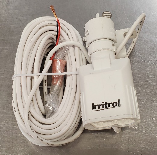
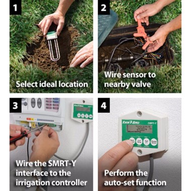
Rain sensors are available so that water isn’t wasted on days where it isn’t needed. These are usually of a variety that are specific to each brand of controller. Consult manufacturers’ literature for guidance on installing them.
Soil sensors do for below-ground moisture levels what rain sensors due for conditions above-ground. If enough moisture is detected in the soil at the sensor’s location, the controller will adjust the run times to suit.
Wifi-enabled controllers are available that allow their settings to be modified via computers and smartphones. This may be advantageous when the changing of settings needs to be done remotely.
If a house is on a rural property, its potable water supply is likely from a well, in which case the house’s potable water connection and irrigation system supply is no different than one that would be served by a municipal utility’s supply. On the other hand, if a pump is used to pull water from a creek or pond specifically for irrigation, then a pump start relay is wired to the controller so that the controller’s power supply can operate the pump’s 120 VAC or 240 VAC on/off control. Again, consult the equipment manufacturer’s literature for compatibility and installation instructions.
Step 10: Routine Maintenance and Troubleshooting
Once a system is filled and commissioned, usually in the late spring or early summer just as the need to irrigate arrives, there is not normally much maintenance required until end-of-season shutdown. A few routine maintenance items to consider may be:
- If damaged heads need to be replaced, dig out enough of the surrounding ground so that the head can be unscrewed from its male threaded connection without allowing dirt to slough into the hole and into the up-facing adapter.
- If pipe gets damaged due to penetrating tools such as a shovel or from winter freezing, dig out around and under the break so that two repair couplings and a short “pup” piece of pipe may be installed.
- If the water supply is hard due to calcium and magnesium content, the nozzles may become partially plugged over time and spray erratically. Nozzles can be immersed in a de-scaling solution and reinstalled, or be replaced, so have replacement nozzles on hand.
- Under normal circumstances the piping should stay clear of obstructions, however it may be necessary to periodically remove the sprinklers and flush the system. Do this in the same manner as when the system was initially flushed, removing one head at a time, starting with the most distant one.
Winterizing
All climates in Canada are prone to winter freeze. None are exempt so plan on draining or blowing out the system with compressed air once the watering season is over. It is extremely difficult, although not impossible, to drain a system by gravity. Blowing it out using compressed air is the norm. Here are the steps involved.
- Close the water supply valve and drain any water from the piping between the source and the zone valves if possible.
- If the backflow preventer is installed in a heated area, open all the test ports and place the ball valves in the half-open position. This will allow the cavity between the ball and the valve body to drain as well.
- If the backflow preventer is installed below ground or in an area where it may freeze, it should be removed. It will have to be replaced and re-tested in the spring. Plug any open pipe ends to prevent debris and insects from entering the open piping.
- Make sure there is a blowout fitting installed immediately downstream of the backflow preventer. This is where air will be introduced. If the backflow preventer is meant to be removed, make sure to install a shutoff between the preventer and blowout fitting; close the shutoff. If the backflow preventer is meant to remain installed after winterizing, a downstream valve would be redundant and need not be installed, in which case close the #2 shutoff on the backflow preventer
- Using a large rotary compressor (best) or a smaller high-volume variety, introduce compressed air at the blowout fitting, making sure to not exceed the maximum pressure allowance for the component with the lowest pressure threshold. 50 to 75 psi (345 to 515 kPa) is adequate to do the job.
- Open one zone valve at a time and let the air push all the water from the piping. Close the zone valve when no water mist is apparent from all the sprinklers in the zone.
- Go around the system and bleed each zone at least twice. This will pick up and move any water that tends to settle back into the low spots in the piping after the air flow stops.
- Once the blowout is finished, make sure that the handles of any ball valves that may freeze are left in the 45-degree position, to prevent the valve bodies from breaking.
It is important to note that it is more the volume of air that is needed rather than air pressure. A sustained volume of air ensures that water is completely pushed out of the system. If a low-volume compressor is used, it may take several cycles of zone opening/closing to satisfactorily get rid of all the water in the system.
Now complete Self-Test 3 and check your answers. Answers are at the end of this learning guide.
Self-Test 3
Self-Test 3
- Correctly complete the following statement: “Electrical cables for irrigation zone valves must be …..”
- nylon-jacketed
- acceptable for direct earth burial
- made up of stranded aluminum wires
- of the same type used in house construction
- What is the most common gauge of wire used for residential sprinkler systems?
- #12 AWG
- #14 AWG
- #16 AWG
- #18 AWG
- What does Toro® call their composite pipe used on barb fittings at sprinkler locations?
- “Weird Pipe”
- “Funny Pipe”
- “Ridiculous Pipe”
- “Composite Pipe”
- When trenching through an existing lawn, what is a good way to minimize the amount of final cleanup required on the lawn?
- Discard the sod and lay the spoils on plastic
- Place the removed sod and spoils on plastic on the same side of the trench
- Remove all sod and spoils and truck them away; replace with fresh dirt and re-seed
- Place the removed sod on plastic on one side of the trench, spoils on the other side also on plastic
- What is a relatively easy way to get a pipe under an existing concrete sidewalk?
- By “jetting” it
- By pre-planning for it when the house was being built
- By jackhammering out one section of sidewalk and re-pouring it
- By cutting a narrow trench through the sidewalk and refilling the trench
- What type of connectors are used for wiring at the zone valve locations?
- Soldered
- Marrettes®
- Waterproof twist-on
- Crimp-type within a sleeve
- Which response listed below would be the recommended method of flushing the zone piping (zone valve to sprinklers)?
- Leave all heads off and open the zone valve
- Install all heads on the zone and manually open the zone valve
- Install all but the furthest head, open the valve and flush through the open end
- Leave off all heads at first, then open and close the zone valve after each head is installed
- How many stations should a controller be capable of operating?
- Only as many as there are zones installed
- At least one more than are currently installed
- At least two more than are currently installed
- Twice as many as there are currently installed
- Using the evapotranspiration rate for a hot/humid climate, calculate the run time for a zone that has sprinklers with an average precipitation rate of 1.06 in (27 mm) per hour, if the zone is being watered 4 days per week.
- 20 minutes
- 25 minutes
- 30 minutes
- 40 minutes
- If a lawn has sandy soil, which one of the following would be the most logical approach to programming the controller?
- Set longer run times, decrease the number of cycles per day and increase watering days
- Set shorter run times, increase the number of cycles per day and increase watering days
- Set longer run times, decrease the number of cycles and decrease watering days
- Set shorter run times, increase the number of cycles and decrease watering days
- If a well is used only for irrigation purposes, what feature does the controller need?
- A transformer
- A separate timer
- A pump start relay
- An extra zone control
- What characteristic of water that contains calcium and magnesium may cause the sprinklers to become plugged over time?
- Debris
- Low pH
- Softness
- Hardness
- Where in the system should a blowout connection for winterizing be installed?
- Downstream of the sprinklers
- Downstream of all zone valves
- Downstream of the backflow preventer
- Upstream of the water supply connection
- How should any ball valves be left after winterizing?
- Half open
- Removed
- Fully open
- Fully closed
- What is the most important aspect of the air supply used to winterize a system?
- Its temperature
- Its pressure
- Its volume
- Its area
Check your answers using the Self-Test Answer Keys in Appendix 1.
Media Attributions
- Figure 1 Swing joint by Okanagan College is licensed under a CC BY-NC-SA licence.
- Figure 2 Waterproof twist-on connectors for underground use by Okanagan College is licensed under a CC BY-NC-SA licence.
- Figure 3 Irritrol® rain sensor by Okanagan College is licensed under a CC BY-NC-SA licence.
- Figure 4 Rain sensor © Irrigation Direct Canada. Used with permission.
