Part 1
Module 6 Competency Test No. 1 Open Book
Learning Outcomes
When you have completed this module, you will be able to:
- Within a one hour time limit, complete a written exam and a lab exercise.
The Inventor book was written with competency based modules. What that means is that you have not completed each module until you have mastered it. The Competency Test module contains multiple choice questions and a comprehensive lab exercise to test your mastery of the set of modules that you completed. There are no answers or keys supplied in a Competency Test module since it is meant to be checked by your instructor. If there are any parts of this module that you have trouble completing, you should go back and reread the module or modules containing the information that you are having trouble with. If necessary, redo as many lab exercises required until you fully understand the material.
If you are Completing this book:
- Without the aid of an instructor, complete the written test and the lab exercise.
- In a classroom with an instructor, the instructor will give instructions on what to do after you have completed this module.
Multiple Choice Questions
Select the BEST answer.
- What keyboard key is used to end the current command?
- CTRL
- TAB
- ESC
- SHIFT
- ENTER
- An Inventor _______________is designed to logically organize, store and manage the valid links to the files that are created for each undertaking.
- 3D Model
- Project
- Design
- 2D Sketch
- Menu
- What command is used to zoom the model or the 2D sketch to display the complete model or sketch in the graphic window?
- ZOOM
- PAN
- ISOMETRIC
- ZOOM ALL
- LOOK AT
- What are all files created in Inventor called?
- Designs
- Drawings
- Files
- 3D Models
- 2D Sketches
- What command is used to change the viewing position of the model or sketch to a known home view or isometric view?
- ZOOM
- PAN
- HOME VIEW
- ZOOM ALL
- LOOK AT
- What is the name of the Inventor file that must be used by the operator when creating any new file?
- Design file
- Drawing file
- Model file
- Template file
- Sketch file
- What term describes the process of applying geometrical relationships of objects to one another in a 2D sketch?
- Object snapping
- Dimensional constraints
- Parametric solid modeling
- Driven dimensions
- Geometrical constraints
- What file extension is assigned to a part file?
- .IPT
- .IJP
- .IAM
- .IDW
- .IPN
- When drawing a base sketch that must be extruded to create the solid model there is a list of rules that should be used. Which one of the following rules is false?
- Select the view with the most complex contour shape.
- Draw the lines using dimensions close to finished dimensions.
- The objects in the sketch must meet at their endpoints and cannot overlap.
- The objects in the sketch must have geometrical constraints applied to control the shape.
- The objects in the sketch cannot be a closed polygon.
- What term describes the process of controlling and reporting the size of the geometry in a 2D sketch?
- Object snapping
- Dimensional constraints
- Parametric solid modeling
- Driven dimensions
- Geometrical constraints
Lab Exercise 6-1
Time allowed: 60 minutes.
| Part Name | Project | Units | Template | Color | Material |
| Inventor Lab Lab 06-1 | Inventor Course | Inches | English-Modules Part (in).ipt | Aluminum – Flat | N/A |
Step 1
Start a new part file with the template: English- Modules Part(in).ipt, and save the file with the name: Inventor Lab 06-1, as shown above.
Step 2
Project the Center Point onto the Base sketch.
Step 3
Draw the Base sketch for the object shown in the figure and apply all of the necessary geometrical constraints to maintain the shape of the sketch. Note the location of X0Y0Z0. (Figures Step 3A and 3B)

Base Sketch [Click to see image full size]

3D Model [Click to see image full size]
Step 4
Insert the necessary driving dimensions to fully constrain the sketch. Add at least 1 driven dimension.
Step 5
Ensure that the sketch is fully constrained and all lines display purple. (Figure Step 5)
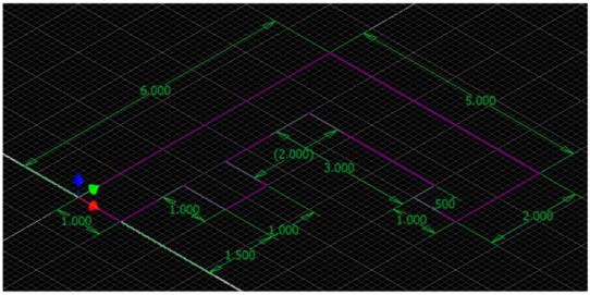
Fully Constrained Base Sketch [Click to see image full size]
Step 6
Extrude the sketch to complete the Base model and apply the color: Aluminum – Flat (Figure Step 6)

Completed Solid Model – Home View
