Part 3
Module 14 Revolving
Learning Outcomes
When you have completed this module, you will be able to:
- Describe a centerline object and explain how it is inserted and used in a 2D Sketch.
- Describe how a Base sketch is revolved with and without the use of a centerline to create a solid model.
- Apply the REVOLVE command to create a solid model from a Base sketch.
Revolving
When drawing symmetrical objects it is much easier to create the model by revolving the Base sketch around an axis rather then extruding it. The axis, which can be one of the lines in the sketch or a centerline, must always be located in the centre of the symmetrical model. The sketch can be revolved any angle between 0 and 360 degrees.
In this module, the basic features of the REVOLVE command are taught. The Inventor Advanced book will cover the more advanced features.
The models in Figure 14-1 and 14-2 were created by revolving the same Base sketch around an axis. Take note how the two solid models that were created using the same sketch are quite different. In Figure 14-1, the line on left side of the sketch was used as the axis while in Figure 14-2, it was the centerline that was used as an axis or revolution.
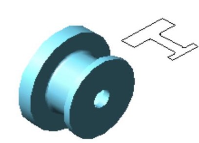
A 2D Sketch Revolved Around a
Line in the Sketch
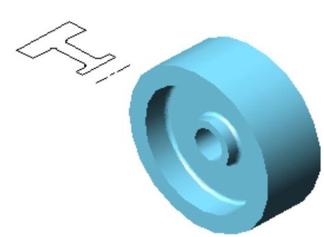
The Same 2D Sketch Revolved
around a Centerline
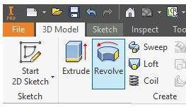
Inventor Command: REVOLVE
The REVOLVE command is used to create a solid model by revolving the Base sketch around an axis.
Shortcut: R
Centerlines
A centerline is a line with its properties set to act as a centerline. In the REVOLVE command, a centerline is automatically recognized as the axis for the revolution. The two methods of drawing a centerline, which is similar to drawing construction a line, are as follows:
Method 1
Draw the line using the LINE command and then select it. While it is selected, click the Centerline icon.
Method 2
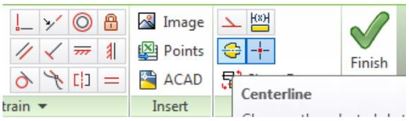
Enable the Centerline icon and then draw the line, using the LINE command. The Centerline icon is shown in Figure 14-3. A centerline will display as the centerline linetype.
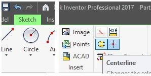
Centerline Icon
WORK ALONG: Revolving a Sketch Without using a Centerline
Step 1
Check the default project and if necessary, set it to Inventor Course.
Step 2
Using the NEW command, start a new part file using the template: English-Modules Part (in).ipt.
Step 3
Save the file with the name: Inventor Workalong 14-1. (Figure Step 3A and 3B)
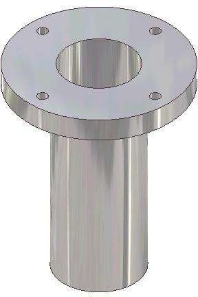
3D Model

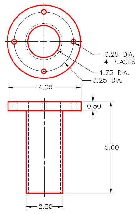
Dimensioned Multiview Drawing [Click to see image full size]
Step 4
Start a new sketch on the Front or XZ Plane. Project the Center Point onto the sketch.
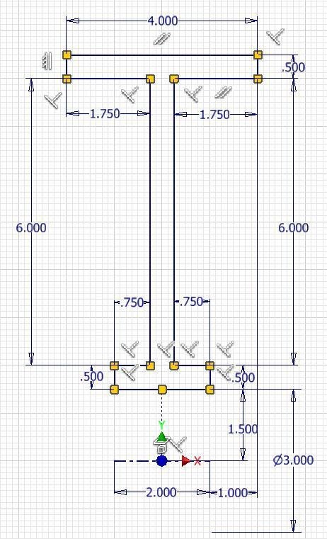
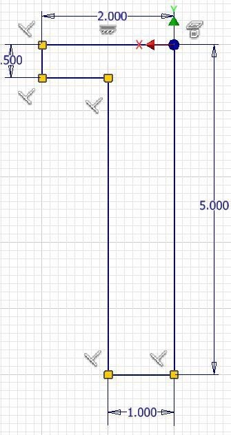
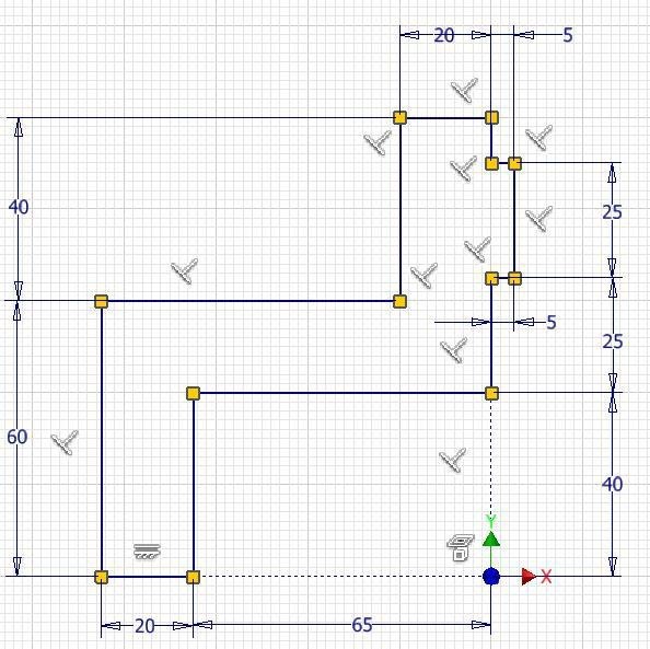
Step 5
Draw and dimension one-half of the Front view as shown in the figure. Ensure that the sketch is fully constrained (Figure Step 5)
Step 6
In Model mode, enter the REVOLVE command. It will highlight the sketch automatically as the area to revolve. (Figure Step 6)

Step 7
In the Revolve dialogue box, set the Extents to Full and enable the Axis icon. Select the line on the right side of the sketch as the axis. The Full setting means that it will be revolved 360 degrees. (Figure Step 7)

Step 8
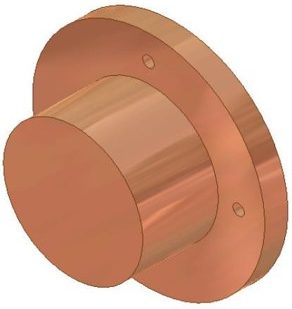
After you select the axis, the REVOLVE command will display the Base model as it is revolved. If this is the desired outcome, click OK. (Figure Step 8A and 8B)

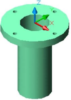
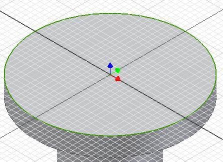
Step 9
Start a new sketch on the top plane of the model. (Figure Step 9)
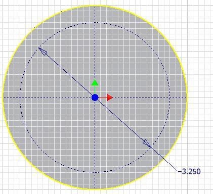
Step 10
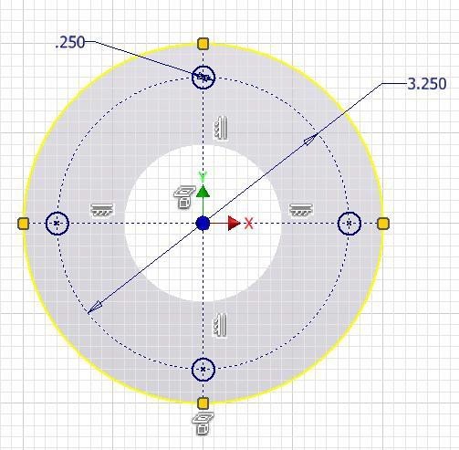
Using what you learned in Module 12, draw a construction circle and four construction lines. Insert a dimension for the diameter of the circle. Ensure that the sketch is fully constrained. (Figure Step 10)
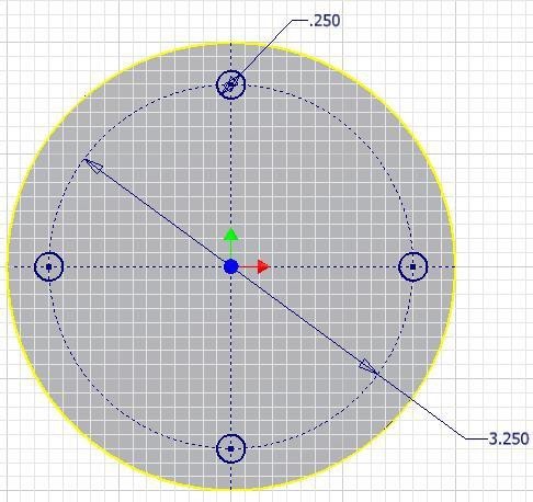
Step 11
Using the technique that you learned in Module 12, draw the 4 circles. Dimension one and constrain the additional 3 with an Equal constraint. (Figure Step 11A and 11B)
Step 12
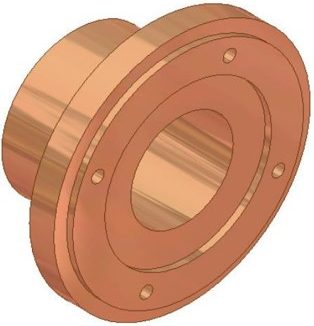
Extrude the four circles to the To Next extents. (Figure Step 12)

Step 13
Start another sketch on the top plane and draw a circle by offsetting the outside diameter. Dimension the circle and extrude it to complete the model. (Figure Step 13)

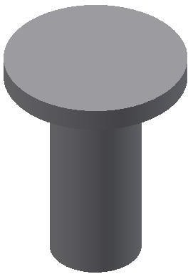
Step 14
Change the colour to: Aluminum – Polished. (Figure Step 14)
Step 15
Save and close the file.
WORK ALONG: Revolving a Sketch using a Centerline
Step 1
Check the default project and if necessary, set it to Inventor Course.
Step 2
Enter the NEW command to start a new part file using the template: English-Modules Part (in).ipt.
Step 3
Save the file with the name: Inventor Workalong 14-2. (Figure Step 3)
Dimensioned Multiview Drawing
Step 4
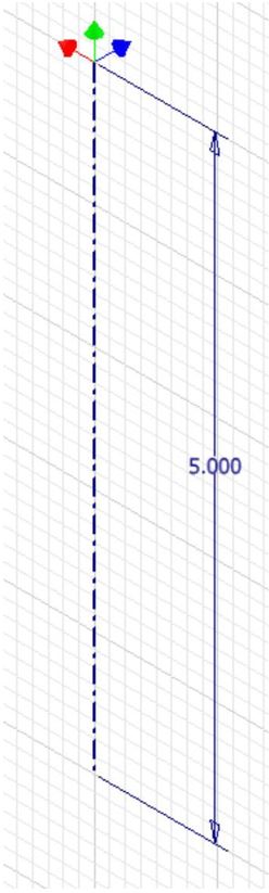
Start a new sketch on the Front or XZ Plane. Draw and dimension a line start it by snapping to the Center Point. Draw it 5 inches in the negative Y direction. This is the length of the model. This is centerline of the solid model. Change the line’s properties to a centerline. (Figure Step 4A and 4B)
Step 5
Draw and dimension one-half of the Front view as shown in the figure. (Figure Step 5A and 5B)


Step 6
Return to Model mode and enter the REVOLVE command. Since a centerline is part of the sketch, the REVOLVE command will automatically use it as the axis to revolve the sketch around. It will display the outcome of the revolution. (Figure Step 6)

Step 7
In a new sketch, add the four smaller circles and extrude them to complete the model.
Step 8
Change the colour to: Aluminum – Polished. (Figure Step 8)
Step 9
Save and close the file.
Drafting Lesson: Cross Sections
When a view of an object requires a clearer description of its interior or it is hard to dimension because of the hidden lines, a cross section view can be drawn in place of the normal multiview. See Figure 32-1
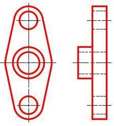
Normal Front and Right Side View of an Object
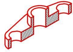
A cross section view, also called a section, is a view of the object as if it were cut along a cutting plane and the two pieces pulled apart exposing the inside of the object. See Figure 32-2 and 32-3.
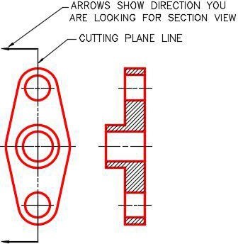
A Front view and Right
Side Section View
3D Model of the Object
Showing it Cut on the
Cutting Plane Line
A cutting plane line is the line along the object where the cut would have been made. See Figure 32-2. The arrows point in the direction that you are looking when drawing the section view. The surfaces of the object that are solid, when cut, are crosshatched.
Key Principles
Key Principles in Module 14
- When drawing symmetrical objects, it is much easier to create the model by revolving the Base sketch around an axis rather then extruding it. The axis, which can be one of the lines in the sketch or a centerline, must always be located in the centre of the symmetrical MODEL.
- A centerline is a line with its properties set to act as a centerline.
Lab Exercise 14-1
Time allowed: 60 minutes.
| Part Name | Project | Units | Template | Color | Material |
| Inventor Lab Lab 14-1 | Inventor Course | Millimeters | Metric-Modules Part (mm).ipt | Copper – Polished | N/A |
Step 1
Project the Center Point onto the Base plane.
Step 2
Note the location of X0Y0Z0. Draw the Base sketch and revolve it create the Base model of the object shown below. Revolve it by using a line in the sketch. Do not draw a centerline. (Figure Step 2A and 2B)

Dimensioned Multiview Drawing

Suggested Base
Sketch – Right Side –
YZ Plane
Step 3
Apply all of the necessary geometrical and dimensional constraints to fully constrain all sketches.
Step 4
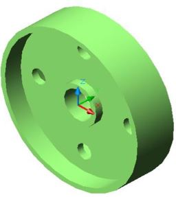
Apply the colour shown above. (Figure Step 4A and 4B)
Completed Solid Model
– Home View
Completed Model
– Rear View
Step 5
Add the four small holes on a new sketch and extrude them.
Lab Exercise 14-2
Time allowed: 60 minutes.
| Part Name | Project | Units | Template | Color | Material |
| Inventor Lab Lab 14-2 | Inventor Course | Inches | English-Modules Part (in).ipt | Zinc | N/A |
Step 1
Project the Center Point onto the Base plane.
Step 2
Note the location of X0Y0Z0. Draw the Base sketch and revolve it create the Base model of the object shown below. Revolve it by using a centerline. (Figure Step 2A, 2B, 2C, 2D, and 2E)
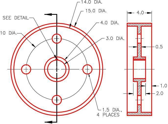
Dimensioned Multiview Drawing
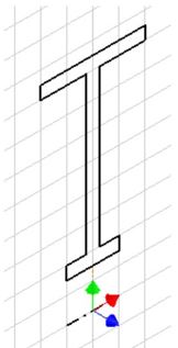
Suggested
Base Sketch –
YZ Plane
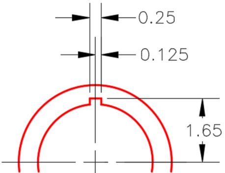
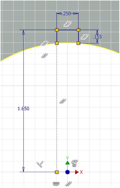
Detail of Keyway
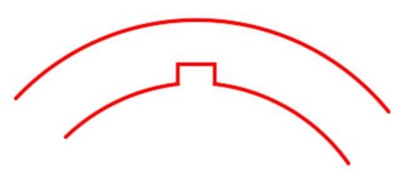
Keyway is Flat Across the Top
Solid Model – Home View
Step 3
Apply all of the necessary geometrical and dimensional constraints to fully constrain all sketches.
Step 4
Apply the colour shown above. (Figure Step 4A and 4B)

Completed Model –
Home View
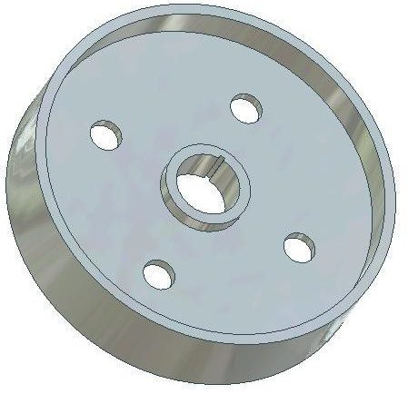
Completed Model
– Rotated View
Step 5
Add the four small holes and the key on new sketches and extrude them.