Part 1
Module 5 Extruding – Part 1
Learning Outcomes
When you have completed this module you will be able to:
- Describe dimensional constraints, linear dimensions, driving and driven dimensions.
- Apply the GENERAL DIMENSION command to insert the necessary linear dimensions to fully constrain Base sketches.
- Describe and apply the EXTRUDE command to extrude Base sketches to create the 3D Base model.
Dimensional Constraints
Unlike geometrical constraints, that are used to apply geometrical relationships between the objects in the sketch, dimensional constraints control and report the size of the geometry. Dimensional constraints are sometimes called parametric dimensions. To fully constrain a 2D sketch, driving dimensions must be applied. A driving dimension is a parametric dimension controlling the size of the object. Inventor will automatically change the overall model to conform to the driving dimensions maintaining the existing geometrical constraints that were assigned in the sketch. Objects of the sketch that are not dimensioned will change to adapt when a driving dimension is applied or an existing driving dimension is changed.
Add only the number of driving dimensions that are required to ensure that the model maintains the desired size and shape. Inventor will issue a warning when a dimension is added that over-constrains the sketch. Only driven dimensions will be allowed to be added to a fully constrained sketch.
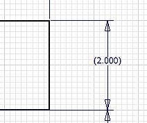
A driven dimension is a non-parametric dimension that does not constrain the object. It only displays the current value of the geometry that it is applied to. Driven dimensions are automatically enclosed in parentheses to distinguish them from driving dimensions. You can add as many driven dimensions to the sketch as you wish.
Base Model
After the Base sketch is complete and is fully constrained, it is ready to be extruded or revolved to create the base model. The Base model is the solid model created from the base sketch by extruding or revolving it. In this module, only extruding the Base sketch to create the Base model is taught. The simplest definition of an extrusion is it adds depth to the Base sketch to create the Base model. See Figure 5-1.
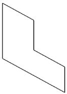
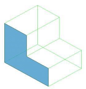
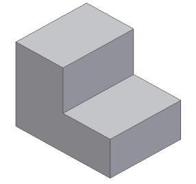
Figure 5-1
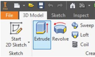
Inventor Command: EXTRUDE
The EXTRUDE command is used to extrude a 2D sketch to create or edit a 3D solid model.
Shortcut: E
Dimensioning Sketches
There are many different types of dimensions available to the operator to dimension sketches. The different dimensioning types will be taught throughout the Inventor book. In this module, inserting object linear dimensions is taught.
Linear Dimensions
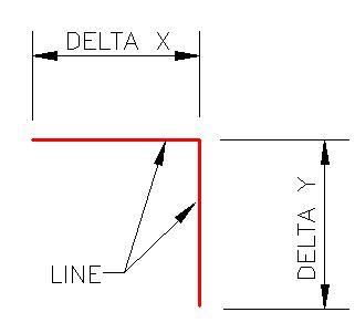
A linear dimension is a dimension measuring the delta X or the delta Y distance between the two XY locations or endpoints of a line. See Figure 5-2. Linear dimensions are always either horizontal (delta X) or vertical (delta Y). A linear dimension cannot be used to dimension the true length of an inclined line. It will only dimension the true length of a line if the line is horizontal or vertical. If both endpoints of a line lie on the same axis, it can only be dimensioned in one delta direction. Since all lines that were drawn to this point in the book were either horizontal or vertical, linear dimensions will be used for all of the dimensions inserted in this module.
Linear Dimensions Applied to
Horizontal and Vertical Lines
Object Linear Dimensions
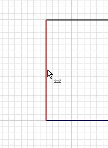
To insert an object linear dimension, enter the GENERAL DIMENSION command and move the cursor onto the line to be dimensioned. When the two headed arrow icon appears, click the left mouse button to select the line as shown in Figure 5-3. After selecting the line, move the cursor in the direction to select the location of the dimension. Click the mouse at the desired location of the dimension.
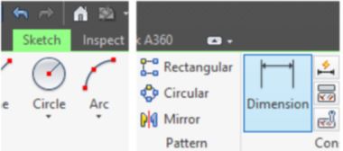
Inventor Command: GENERAL DIMENSION
The GENERAL DIMENSION command is used to create driving or driven dimensions on a sketch.
Shortcut: D
WORK ALONG: Dimensioning and Extruding the Base Sketch
Step 1
Using the OPEN command, open the part file: Inventor Workalong 04-1 that you completed in Module 4.
Step 2
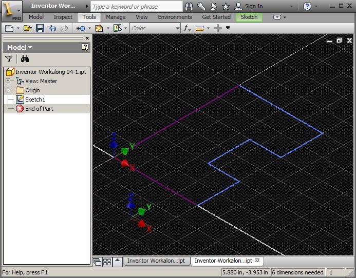
Change to Sketch mode by editing Sketch1 in the Browser bar. Press F6 to change the view to the Home view. (Figure Step 2)
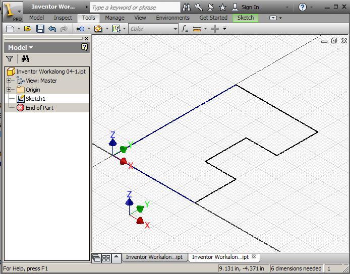
AUTHOR’S COMMENTS: Two lines of the sketch should appear purple and the remainder blue. The purple lines are constrained while the blue ones are not. The reason the two lines are constrained is because they have one endpoint snapped to the Center Point (X0Y0), which is constrained (projected) to the sketching plane. In this workalong, you will be adding dimensional constrains to fully constrain the sketch.
Step 3
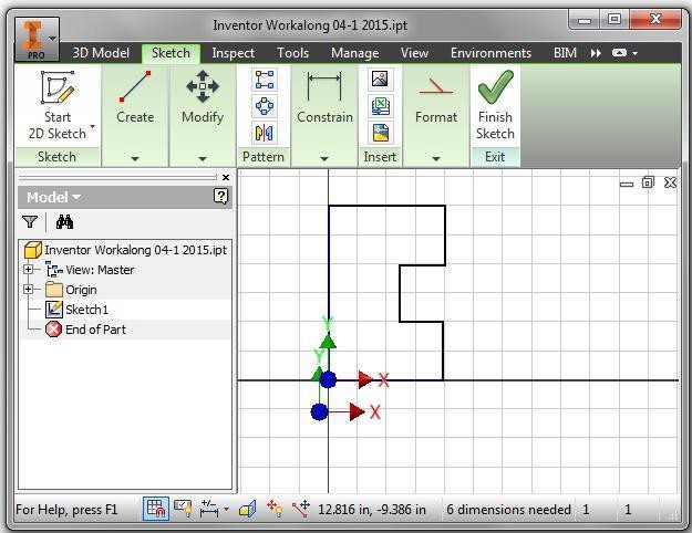
Enter the LOOK AT command and when prompted, select one of the lines on the sketch as shown in the figure. (Figure Step 3A and 3B)
Step 4
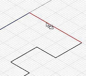
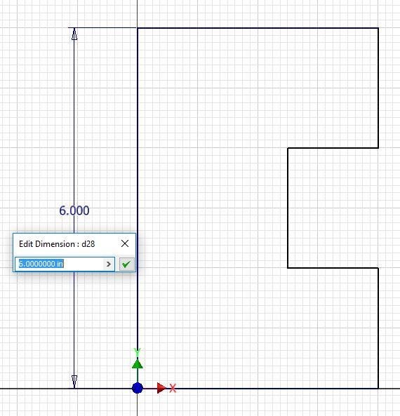
Enter the GENERAL DIMENSION command by pressing D on the keyboard. Move the cursor onto the left vertical line. When the Two Headed Arrow icon appears, select the line by clicking the left mouse button. (Figure Step 4)
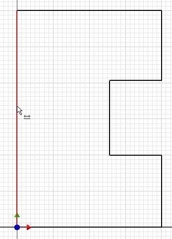
Step 5
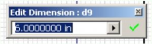
Move the cursor to the left and drag the dimension. Inventor will measure the delta Y length of the line, since it is a vertical line, and display its actual length. In this case, it is 6.0 inches long. Since that is the desired length, accept it by clicking the green Check icon. (Figure Step 5)
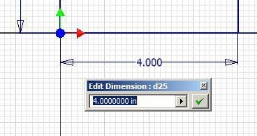
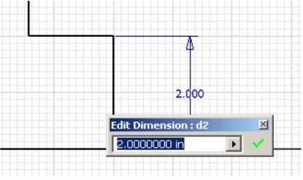
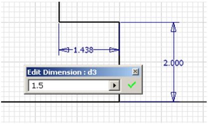
Step 6
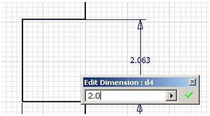
Continue to add linear dimensions to fully constrain your sketch. If the length of the lines are correct, accept the dimension. If they are incorrect, change the dimension in the edit box to the actual dimension of the line and then accept it by clicking the green Check icon. (Figure Step 6A, 6B, 6C, and 6D)
Step 7
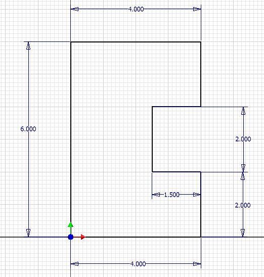
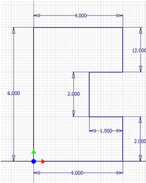
When complete, there should be six driving dimensions. (Figure Step 7)
Step 8
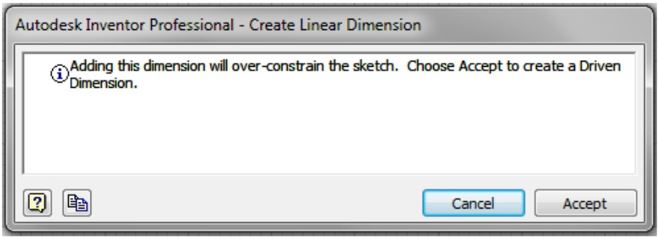
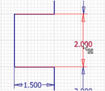
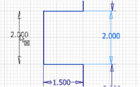
Add one more dimension as shown in the figure. Note that Inventor will issue a warning that the dimension over-constrains the sketch. Click the Accept button to add it as a driven dimension. (Figure Step 8A and 8B)
Step 9
Without entering a command, move the cursor onto the 2.000 dimension as shown in the figure. When the Move icon displays, click and hold the mouse button down and drag the dimension to the new location shown in the figure. (Figure Step 9A and 9B)
USER TIP: Instead of clicking the green Check icon to accept the displayed dimension in the Edit Dimension dialogue box it is faster to press the Enter key.
Step 10
The completed sketch should appear as shown in the figures. (Figure Step 10A, 10B, and 10C)

Step 11
Press F6 to change to the Home view. (Figure Step 11)
Step 12
Click the LOOK AT command and change the view to the top or XY plane.
Step 13
Press F8 to display the geometrical constraint icons. You figure should appears similar as shown in the figure. (Figure Step 13)
Step 14
Enter the EXTRUDE command. The Extrude dialogue box will display. The model being drawn is 5 inches high as shown in the figure. Set the Output box to Solid, the Extents to Distance of 5 and the Extrude Direction to positive Z as shown in the figures. (Figure Step 14A and 14B)

Step 15
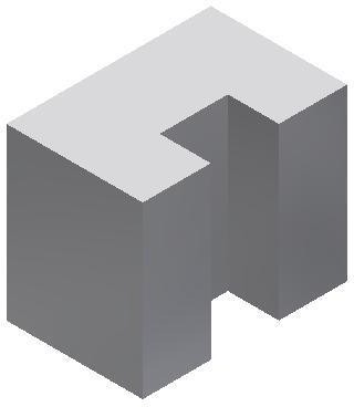
The completed solid model should now appear as shown in the figure. (Figure Step 15)
Step 16
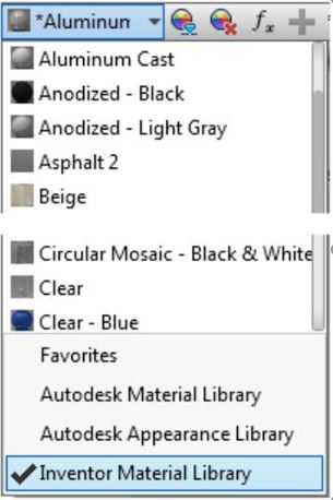
Find the Appearance pull-down menu and select the arrow to pull down the Color list. Ensure that the library: Inventor Material Library is enabled at the bottom of the list. (Figure Step 16A and 16B)

Step 17
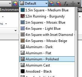
In the Appearance pull-down menu, select the color: Aluminum Polished as shown in the figure. (Figure Step 17)
Step 18
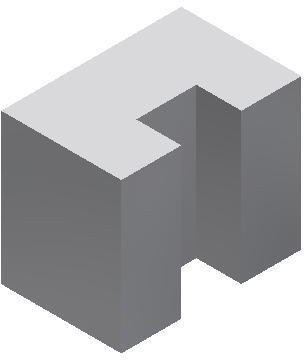
The completed part or model should appear as shown in the figure. (Figure Step 18)
Step 19
Save and close the part file.
MUST KNOW: A driving dimension is a parametric dimension controlling the size of the object. Inventor will automatically change the overall sketch to conform to the driving dimensions maintaining the existing geometrical constraints that were used in the design.
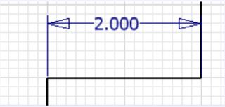
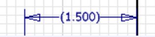
A driving dimension is shown below. A driven dimension is a non-parametric dimension that does not constrain the object. It is inserted for reference only and is always displayed enclosed in brackets as shown below.
USER TIP: When you open the Extrude dialogue box for the first time, the Marking menu will display on top of the extruded model. You will not be using that menu in the Inventor book.

USER TIP: Click the bottom right arrow and enable Pin Mini-Toolbar Position and Auto Fade.
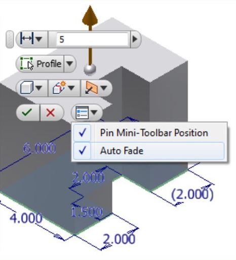
Drag the Marking menu to bottom right corner of the Graphic window. It will remain there for the duration while you working on the Inventor book. After you complete the book, you can use change the settings to use the menu any way the works for you.

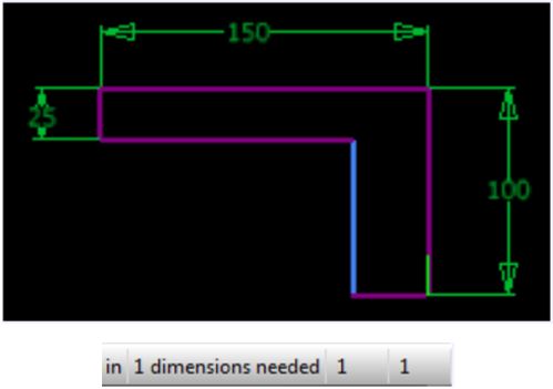
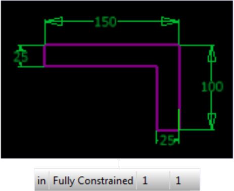
MUST KNOW: Knowing When the Sketch is Fully Constrained It is very important to know when a sketch is fully constrained. A fully constrained sketch is complete and is ready to be extruded or revolved to create or edit the solid model. When the colour scheme is set to High Contrast, the background is black and the lines that are constrained will display purple. The lines that are not yet constrained will display blue. When the sketch is fully constrained, all of the lines in the sketch will display purple. Inventor also reports the current constraint status on the Status bar. See the figures below.
A special Pinned icon will display in Browser bar on sketches that are fully constrained as shown to the figures.
![]()
Key Principles
Key Principles in Module 5
- Unlike geometrical constraints, that are used to apply geometrical relationships of the objects in a 2D sketch, dimensional constraints control and report the size of the geometry.
- To fully constrain a 2D sketch, driving dimensions must be applied. A driving dimension is a parametric dimension controlling the size of the object. Inventor will automatically change the overall object to conform to the driving dimensions maintaining the existing geometrical constraints that were assigned in the sketch.
- A driven dimension is a non-parametric dimension that does not constrain the sketch.
- It is very important to know when the sketch is fully When it is fully constrained, the sketch is complete and it is ready to be extruded or revolved to create the Base model. When the background colour scheme is set to High Contrast the constrained lines will display purple and lines that are not yet constrained will display blue. When the sketch is fully constrained, all of the lines in the sketch will display purple.
- After the Base sketch is complete and is fully constrained, it is ready to be extruded to create the Base model. The Base model is the solid model created from the Base sketch.
Lab Exercise 5-1
Time allowed: 40 minutes.
| Part Name | Project | Units | Template | Color | Material |
| Inventor Lab 04-1 | Inventor Course | Inches | English-Modules Part (in).ipt | Zinc Chromate 2 | N/A |
Step 1
Open the file: Inventor Lab 04-1.ipt that you saved in Lab Exercise 4-1 in Module 4.
Step 2
Using the SAVEAS command, save the file with the name: Inventor Lab 05-1.ipt.
Step 3
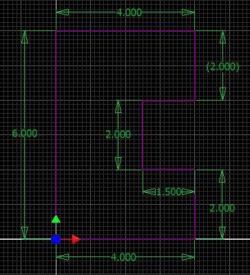
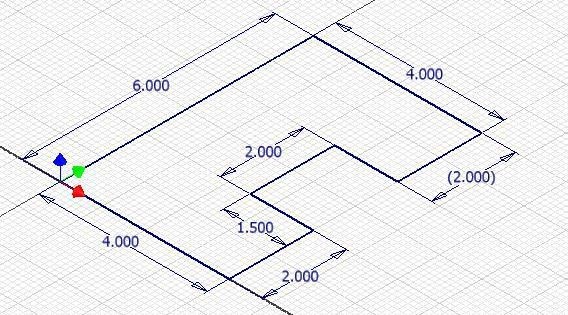
Insert the necessary driving dimensions to fully constrain the sketch. Add at least one driven dimension. (Figure Step 3A, 3B, and 3C)
3D Model
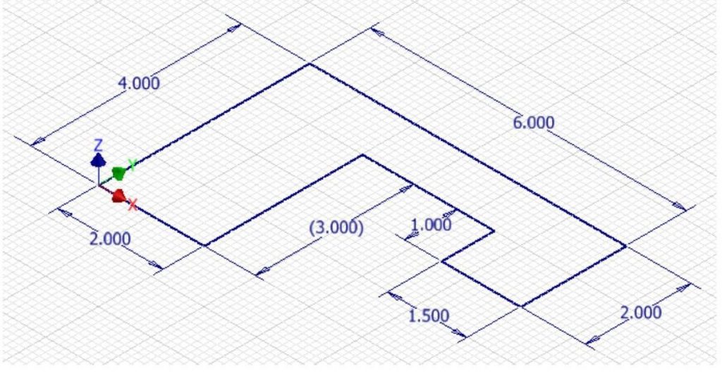
Base Sketch Dimensioned

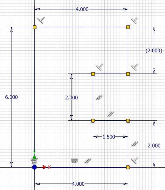
The Base Sketch Fully Constrained [Click to see image full size]
Step 4
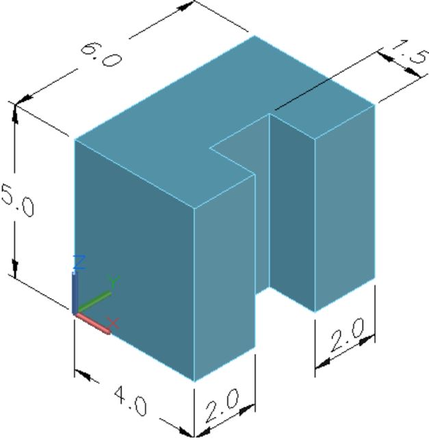
Extrude the sketch to create the Base model and apply the colour shown above. (Figure Step 4)
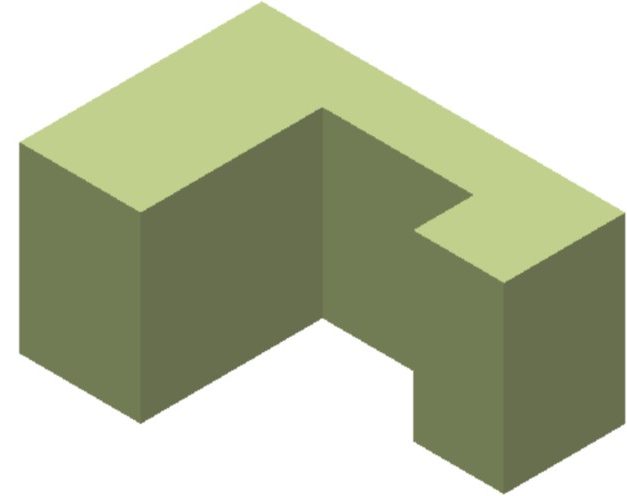
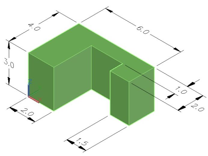
Completed
3D Solid Model
Home View

Lab Exercise 5-2
Time allowed: 40 minutes.
| Part Name | Project | Units | Template | Color | Material |
| Inventor Lab 04-2 | Inventor Course | Inches | N/A | Chrome – Polished Blue | N/A |
Step 1
Open the file: Inventor Lab 04-2.ipt that you saved in Lab Exercise 4-2 in Module 4.
Step 2
Using the SAVEAS command, save the file with the name: Inventor Lab 05-2.ipt.
Step 3
Insert the necessary driving dimensions to fully constrain the sketch and add at least two driven dimensions. (Figure Step 3A, 3B, and 3C)
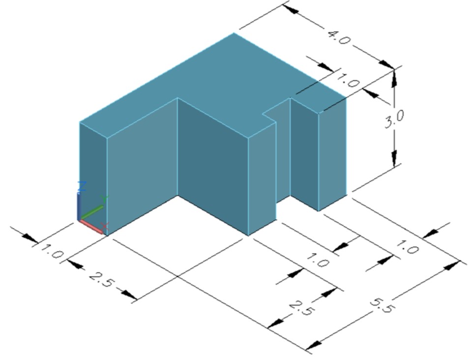
3D Mode

Base Sketch Dimensioned [Click to see image full size]

Base Sketch Fully Constrained [Click to see image full size]
Step 4
Extrude the sketch to create the Base model and apply the colour shown above. (Figure Step 4)
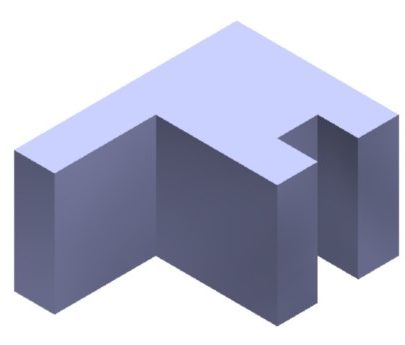
Completed 3D Solid Model
Home View
AUTHOR’S GEOMETRIC CONSTRAINS: The following figure shows the Base sketch’s construction method plus geometric and dimensional constraints suggested by the author to help you learn how to construct and constrain sketches. It is only the suggested method and if you can complete a fully constrained sketch using a different construction method and constraints, that is what is important. You may want to compare your construction method and constraints used with the authors.

