Part 4
Module 20 Modifying Solid Models
Learning Outcomes
When you have completed this module, you will be able to:
- Describe how to edit the dimensions and part features of an existing solid model using the Browser bar to aid you.
- Describe how to hide and/or suppress features in the solid model.
- Describe and apply the MEASURE command to measure lengths, loops, angles, or areas of a solid model in either two dimensions or three dimensions.
- Describe how to set the material and change the colour of faces of the solid model.
- Describe how to obtain the physical properties of a solid model.
Modifying Solid Models
The ability to modify solid models is as important to the drafter/designer as being able to construct models. Since most parts are modified after the initial design or revised and used in another project, it is very important that you can modify solid models rather then redraw them. The true power of Inventor is its ability to modify a solid and have it conform to the geometrical and dimensional constraints applied to it when it was constructed without having to redraw it. In this module, the basics of modifying solid models is taught. The Inventor Advanced book will cover the more advanced methods of modifying solid models.
Working with the Browser Bar
The Browser bar is used extensively as a tool to assist you when modifying solid models. It displays the work features and the part features for the current part.
Features
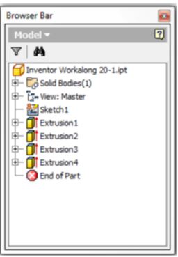
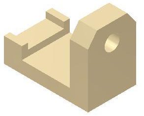
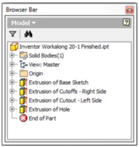
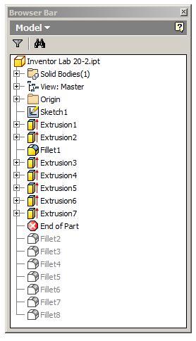
Work features are the basic sketching planes (XY, XZ, YZ), the axes (X, Y, Z) and the Center Point as shown in Figure 20-1. Part features are the 3D features added to the solid model in model construction. The part features for the active part are shown in Figure 20-2.
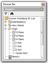
Work Features
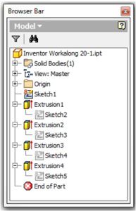
Part Features
Edges and Faces
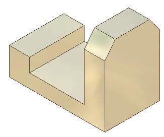
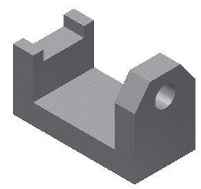
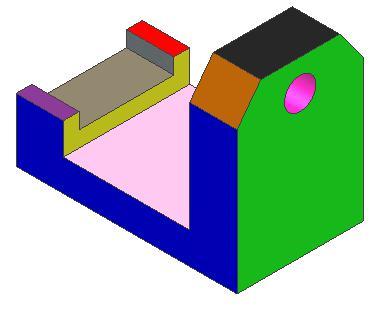
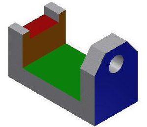
Edges are the lines, circles, or arcs located between the planes that form the solid model. Faces are the planes between the edges of the solid. A face can also be circular or cylindrical in shade, for example the hole in the model. Figure 20-3 shows each visible face of a solid model in a different colour.
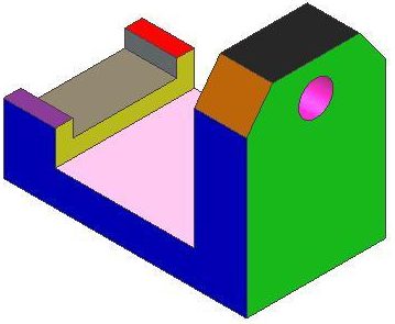
Edges and Faces
WORK ALONG: Modifying a Solid Model
Step 1
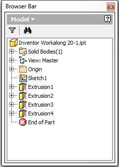
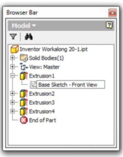
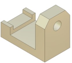
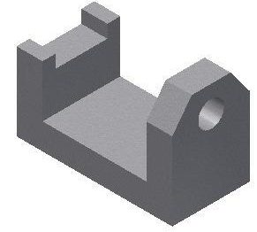
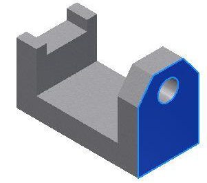
Open the part file: Inventor Workalong 20-1.ipt. This is one of the parts that you received when you download your book. It should be in the folder: Lab Exercise. (Figure Step 1A and 1B)

Step 2
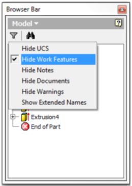
The Filter icon located at the top of the Browser bar allows you to enable or disable the visibility of the features in the Browser bar. Click the Filter icon. The filter list will display. (Figure Step 2A and 2B)


Step 3
Click Hide Work Features to enable it. The work features are now hidden for the current part. (Figure Step 3A and 3B)
Step 4
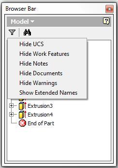
Since you want the work features to display most of the time, click the Filter icon again and disable the Hide Work Features. (Figure Step 4)
Step 5
The Part icon is the first icon inside the Browser bar window. It displays the name of the active part. (Figure Step 5)
Step 6
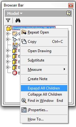
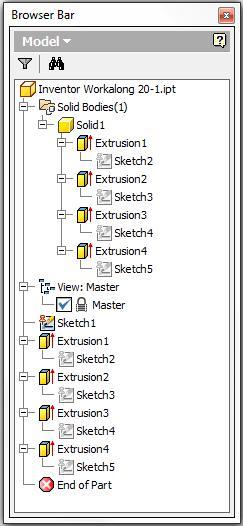
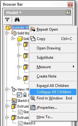
Right-click the part name. In the Right-click menu, click Expand All Children. Note how all the folders and part features will expand to display every feature in the current part. Right click the menu again and this time, click Collapse All Children. (Figure Step 6A, 6B, and 6C)
Step 7
Right-click the part feature Extrusion1. In the Right-click menu, click Show Dimensions. Note how the 2D sketch dimensions and the extrusion dimension will display on the model. (Figure Step 7)

Step 8
Right-click Extrusion1 again. In the Right-click menu, click Edit Sketch. The Graphic window will change to Sketch mode and display the sketch. (Figure Step 8)
Step 9
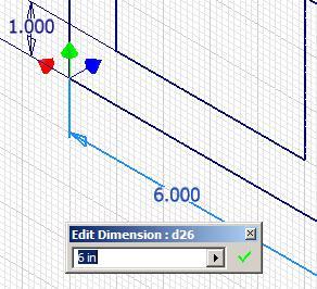
Double click any dimension in the sketch and the Edit Dimension dialogue box will open as shown in the figure. You could now change the dimension, if required, which in turn will change the size of the model. Close the dialogue box without making any changes and return to Model mode. (Figure Step 9)
Step 10
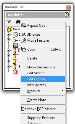
Right-click Extrusion1. In the right-click menu, click Edit Feature. Since this feature is an extrusion, the Extrude dialogue box will open. If required, the extrude feature could be edited. Click the Cancel button to close it. (Figure Step 10A and 10B)

Step 11
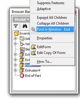
Right-click Extrusion3 as shown in the figure. In the right-click menu, click Find in Window. Note how the extrude on the left side will fully display in the window. This is a handy feature to use when your part is complicated or if you are using a part you are not familiar with. (Figure Step 11)
Step 12
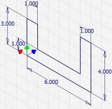
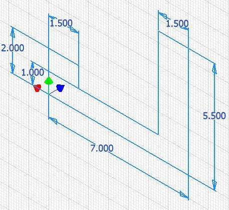
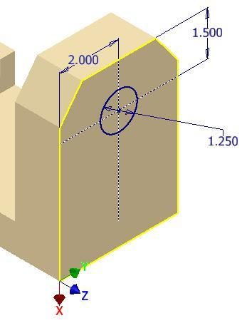
Using what you learned in Steps 8 to 11, edit the sketch in Extrusion1 to match the dimensions shown in the figure. When you are done, click Finish Sketch to return to Model mode and the model will resize to reflect the changes you made to the dimensions. (Figure Step 12)
Step 13
Edit Extrusion1 to change the extrusion depth from 3 inches to 4 inches. Click OK. (Figure Step 13)

Step 14
Edit the dimensions in the sketch for the part feature Extrusion4 to the dimensions shown in the figure. Return to Model mode. (Figure Step 14A and 14B)
Step 15
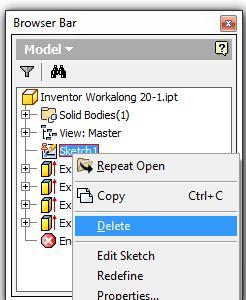
Since Sketch1 is an unconsumed sketch, it can be deleted. Select it and right click it. In the Right-click menu, select Delete. (Figure Step 15)
Step 16
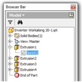
Expand the children. Change the name of Sketch2 to Base Sketch – Front View. (Figure Step 16A and 16B)
Step 17
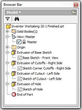
Change the names of all the part features and their children to match the names in the figure. Change the name of the part to: Inventor Workalong 20-1 Finished.ipt as shown in the figure. (Figure Step 17)
Step 18
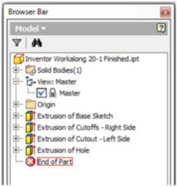
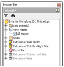
Move the cursor onto the End of Part icon and hold down the left mouse button. When the End of Part has a red rectangle around it, drag it to the location shown in the figure. (Figure Step 18A, 18B, and 18C)
Step 19
Drag the End of Part icon back to the bottom of the part feature list in the Browser bar. (Figure Step 19A and 19B)
Step 20
Using the SAVEAS command, save the file with the name: Inventor Workalong 20-1 Finished. Close the part.
Measuring the Model
Inventor has four commands available to measure distances, angles, loops lengths and areas. They also allow the user to set the units and decimal precision of how it displays the answers. Answers can be accumulated. Measurements can be made in either 3D (Model mode) or 2D (Sketch mode).
Inventor Command: MEASURE DISTANCE, MEASURE ANGLE, MEASURE LOOP, MEASURE AREA
The MEASURE command is used to measure distances, angles, loops lengths and areas. It can be used in model mode or sketch mode. If it is used in Model mode, it measures in 3D and in Sketch mode, it measures in 2D.
Shortcut: None
WORK ALONG: Measuring a Solid Model
Step 1
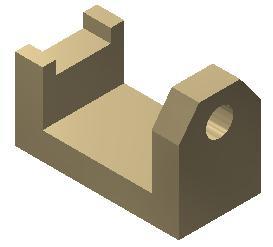
Open part file: Inventor Workalong 20-1.ipt. (Figure Step 1)
Step 2
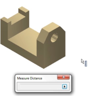
Click the MEASURE DISTANCE command. The Measure Distance dialogue box will display as shown in the figure. Move this dialogue box close to your model to make measuring easier. (Figure Step 2).
Step 3
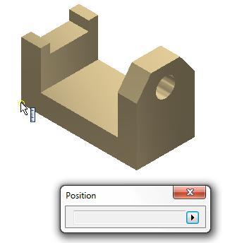
Note that when you are in Measuring mode, the Graphic cursor appears as a ruler icon. The ruler icon indicates that you are measuring in document units. This will be covered in greater detail later in the module. (Figure Step 3)

Step 4
Move the cursor to the bottom left corner of the model and click the left mouse button. Note how it displays a small snap circle indicating that you are snapping to an exact endpoint. (Figure Step 4)
Step 5
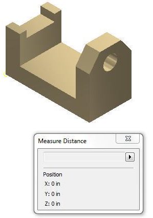
When you snap to a location on the model, the XYZ coordinate location will display as shown in the figure. In this case, it is X0Y0Z0 of the model or the Center Point. (Figure Step 5)
Step 6
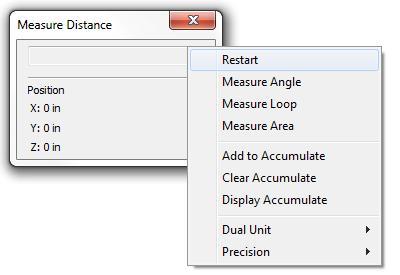
To clear the Measure Distance dialogue box and start a new measurement, click the small triangle inside the dialogue box. In the pull-down menu, select Restart. (Figure Step 6)
Step 7
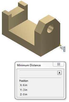
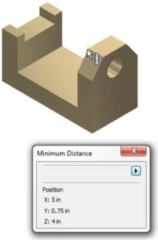
Move the cursor to bottom right corner of the right side of the model. Click it to snap to the corner. The XYZ location will display in the dialogue box as shown in the figure. (Figure Step 7)
Step 8
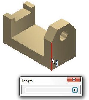
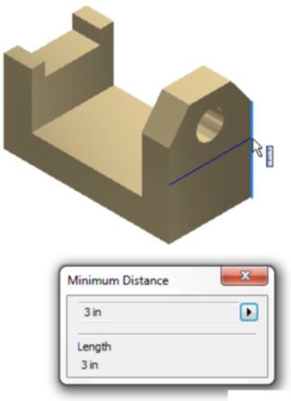
Clear the dialogue box by clicking Restart. Measure the length of an edge. Move the cursor onto the left edge of the right side of the model as shown in the figure. (Figure Step 8)
Step 9
When you click the mouse, the length of the edge will display in the dialogue box. In this case, it is 3 inches long. (Figure Step 9)
Step 10
While the dialogue box is still displaying the length of the edge, click the opposite edge. Note how the dialogue box now displays both the length of the edge and the distance between the edges. A line showing the measured distance will display to show you what is being measured. (Figure Step 10)
Step 11
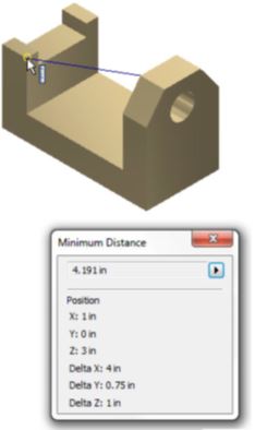
To measure a three dimensional distance, click the two corners shown in the figure. The 3D dimension between the corners will display as well as the XYZ location of the last corner and the delta XYZ distances. (Figure Step 11A and 11B)
Step 12
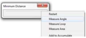
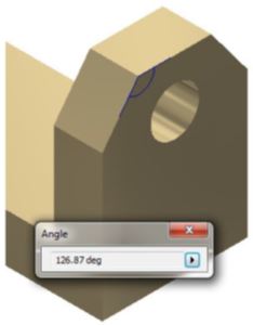
Measure the angle between the two edges by clicking the small triangle at the end of the dialogue box. In the pull-down menu, select Measure Angle. Select the two edges. The angle will display graphically and as an exact number in decimal degrees. (Figure Step 12A and 12B)
Step 13
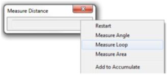
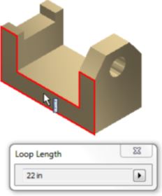
Change the command to Measure Loop. Click the face on the Front view. Note how the complete loop (the perimeter) around the front plane will highlight and the loop distance of 22 inches will display in the dialogue box. (Figure Step 13A and 13B)
Step 14
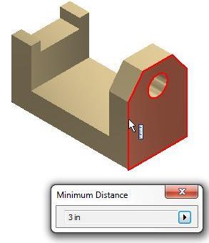
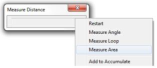
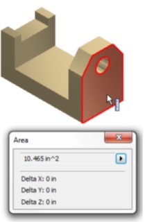
Measure the area of the right side face by changing the command to Measure Area. Click the face on the right side and the area to be measured will highlight. The area will display in the dialogue box. Since there is a hole in this plane, the area will be measured minus the hole. (Figure Step 14A and 14B)
Step 15
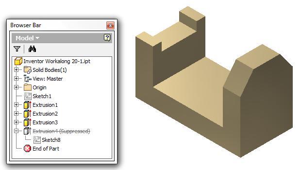
Suppress the hole feature on the right side face so that you can measure the area of the face without subtracting the hole. Right-click the feature in the Browser bar. In the Right-click menu, select Suppress Feature. Note how Extrusion4 is now grayed out. (Figure Step 15)
Step 16
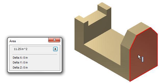
Using what you just learned, measure the area of the right-side minus the hole. After you measure it, unsuppress the hole feature. (Figure Step 16)
Step 17
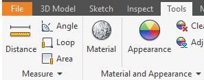
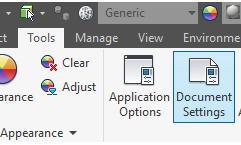
Click Tools and then click Document Settings. This will open the Document Setting dialogue box for the current part. Do not make any changes at this time. Click Close to close the dialogue box. (Figure Step 17A and 17B)
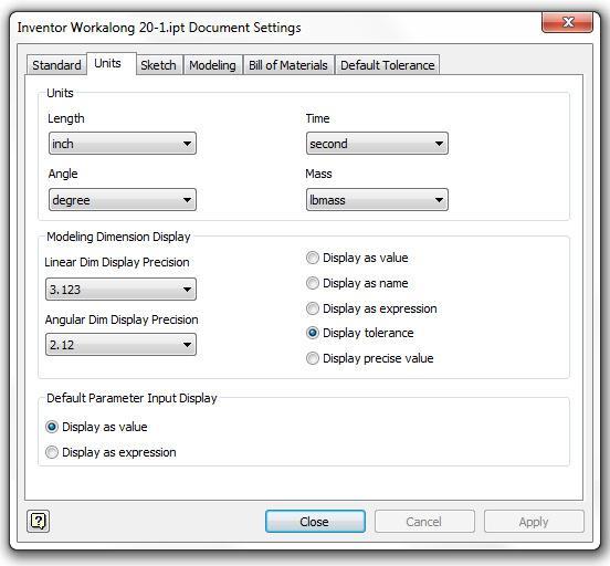
Step 18
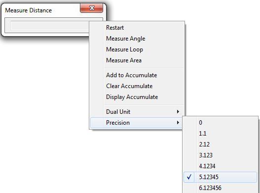
Enter the MEASURE command. Click the small triangle at the end. In the pull-down menu, select Precision and then 5 places. An example of an area measurement with a precision of 5 decimals points is shown in the figure.
Step 19
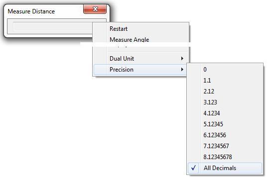
Change the precision to display All Decimals. A sample of an answer to an area measurement is shown in the figure. (Figure Step 19)
Step 20
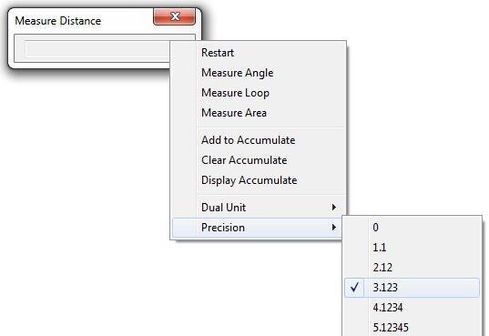
Change the precision back to three decimal places. (Figure Step 20)
Step 21
Change the colour to: Aluminum Cast. (Figure Step 21)
Step 22
Save and close the part.
Geometry Lesson: Physical Properties
| Mass: | the quantity of the matter contained in the solid model. This is determined by multiplying the volume of the solid times the density of the material it is made from. Mass is not dependent on gravity which makes it different but proportional to the weight. Mass is used when considering a measure of a solid’s resistance to inertia. |
|---|---|
| Volume: | The amount of space occupied by the solid model. |
| Density: | The weight of material usually expressed per cubic inch or cubic millimeter. i.e. 21.55^3in or 42.87^3mm |
| Center of Gravity: | Geometrical centre of the solid model. It is also called the centroid. If the density of the solid is uniform, the centre of gravity or centroid is located at the centre of the mass. |
| Mass = | Volume X Density Expressed as lbmass, grams or kg |
| Area = | Length X Width of a 2D plane. Expressed as sq in or sq mm. ie. 10.5^2in or 23.5^2mm |
| Volume – | cubic inches or millimeters. Expressed as cu in or cu mm ie. 120.5^3in or 55.3^3mm |
| lbmass – | pounds |
| kg – | kilograms 1 kg = 1000 grams 1 kg = 2.2 pounds |
| in – | inches |
| mm – | millimeters 1 in = 25.4 mm |
| Inventor will display answers in scientific notation to control the number of decimals displayed: | For Example 1,250,000 = 1.25E+006 (move the decimal 6 places positively) 0.0001 = 1.0E-004 (move the decimal 4 places negatively) |
Face Coloring
Sometimes it is helpful to be able to change the colour of a face. This is especially helpful when working with complex parts or to display different textures on a model. For example, this can happen during manufacturing when a part is cast and has machined surfaces. By applying the cast material to the part and then changing the faces of the machined areas to a polished texture/color, the model will appear more realistic.
A face colour overrides the part colour and, if applicable, the feature colour for selected faces. In this module, only faces coloring will be taught. The general rules when changing the colour of faces are:
- A face colour overrides the part feature colour which in turn overrides the part colour.
- If the part has been assigned a transparent colour, the face colour you apply will change the colour but it will be transparent.
- If a thread texture is applied to the feature, a change to the face colour affects the base colour used in the thread texture.
- If the face colour has been changed and the feature is colored as a pattern, the patterned features will not display the face colour.
Edges and Faces
Physical Properties
The physical properties of a solid model include the mass, volume, centre of gravity, and inertial properties. Using the physical properties helps you to evaluate how the designed model correlates to its physical counterpart. For example, the weight of a solid model made from different materials could easily be found.
Assigning the Material to the Model
Up to this point in the book, only colour or texture has been assigned to the solid model. In this module, assigning the actual material that the part is made from will be taught.
WORK ALONG: Coloring Faces and Working with Physical Properties
Step 1
Open part file: Inventor Workalong 20-1.ipt. (Figure Step 1)
Step 2
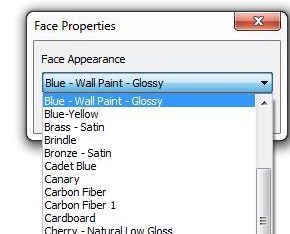
Click the right side face to select it and right click the mouse. In the Right-click menu, select Properties. In the Face Properties dialogue box, select: Blue – Wall Paint – Glossy. (Figure Step 2A, 2B, and 2C)

Step 3
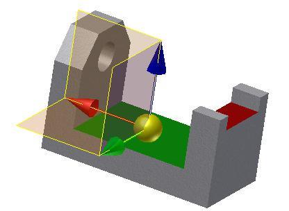
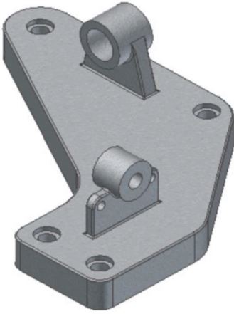
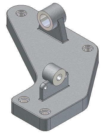
Using what you just learned, change three additional faces as shown in the figure to Green, Orange and Red. (Figure Step 3)
Step 4
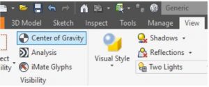
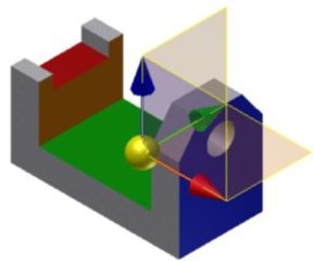
Click the View tab. Click the CENTER OF GRAVITY command. Note how the Center of Gravity icon will display located at the centre of gravity or centroid of the model. It also displays the positive X, Y and Z axis. (Figure Step 4A and 4B)
Step 5
Rotate the model so that you can see the location of Center of Gravity icon from a better viewpoint . (Figure Step 5)
Step 6
Disable the display of the Center of Gravity icon.
Step 7
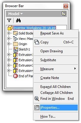
Right-click the part name in the Browser bar. In the Right-click menu, select iProperties. This will open the Properties dialogue box for the current part. (Figure step 7A and 7B)

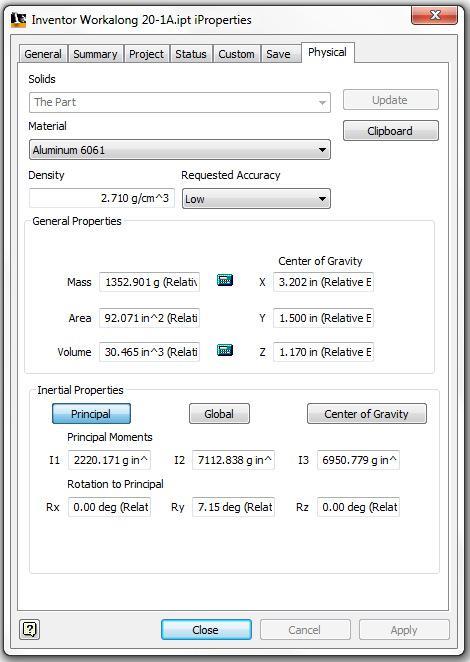
Step 8
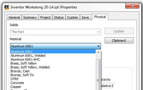
Enable the Physical tab. Note how the material is shown as Default. Pull down the Material list and select: Aluminum 6061. (Figure Step 8)
Step 9
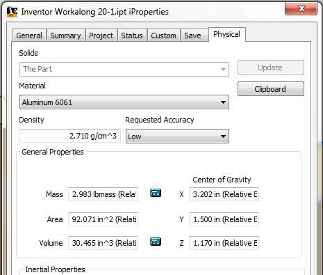
Change the Requested Accuracy to Very High. The Density box displays the density of the material: Aluminum 6061. (Figure Step 9)
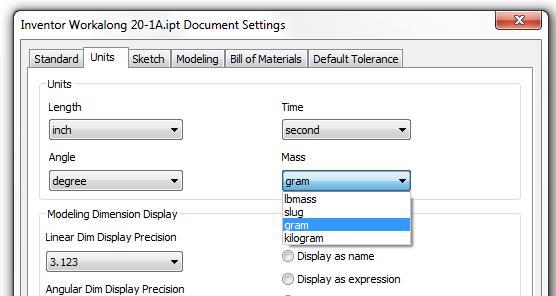
Step 10
Using what you learned earlier in the workalong, open the Document Settings dialogue box and in the Units tab, change the Mass to gram. (Figure Step 10)
Step 11
Note how the mass (weight) is now displayed in grams. (Figure Step 11)
Step 12
Change the material to: Cast Steel. Note how the density and the mass change since steel is much denser then aluminum.
Step 13
Change the material back to: Aluminum-6061. Close the Properties dialogue box.
Step 14
Save and close the part.
Key Principles
Key Principles in Module 20
- The Browser bar is used extensively as a tool to assist you when modifying solid models.
- Work features are the basic sketching planes (XY, XZ, YZ), the axes (X, Y, Z) and the Center Point. Part features are the 3D features added to the solid model in model construction.
- Edges are the lines, circles or arcs located between the planes that form the solid model. Faces are the planes between the edges of the solid.
- Inventor has four commands available to measure distances, angles, loops lengths, and areas. They also allow you to set the units and decimal precision of how it displays the answers. Answers can be accumulated. Measurements can be made in either 3D (Model mode) or 2D (Sketch mode) mode.
Lab Exercise 20-1
Time allowed: 60 minutes.
| Part Name: Inventor Lab 20-1 | Project: Inventor Course | Units: Millimeters |
| Template: Metric – Modules Part (mm).ipt | Color: Aluminum (Cast) | Material: Aluminum – 6061 |
Step 1
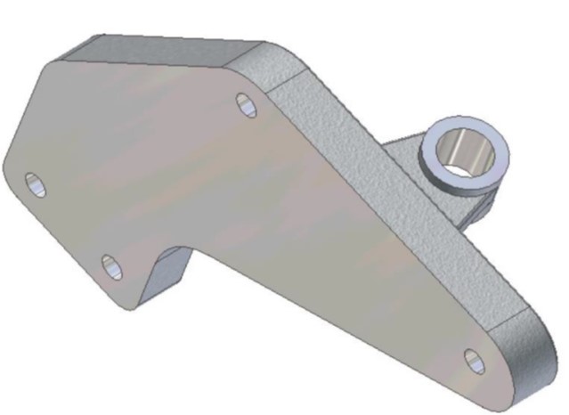
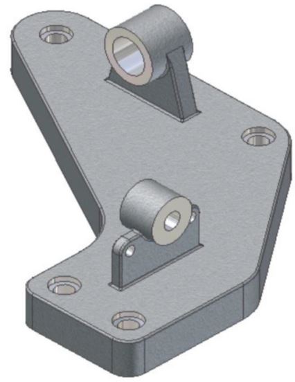
Open the part: Inventor Lab 19-3.ipt that you created in Module 19. (Figure Step 1)
Modified Solid Model
Step 2
Save the file as: Inventor Lab 20-1.
Step 3
Change the model colour to: Aluminum (Cast).
Step 4
Expand All the Children in the Browser bar.
Step 5
Edit the Base sketch and change the dimensions of the overall length from 180 to 200 and the overall width from 140 to 175 in the figure. (Figure Step 5)

Editing the Base Sketch [Click to see image full size]
Step 6
Edit the feature Extrusion1 and change the thickness of the base sketch from 15mm to 20 mm. Return to model mode.
Step 7
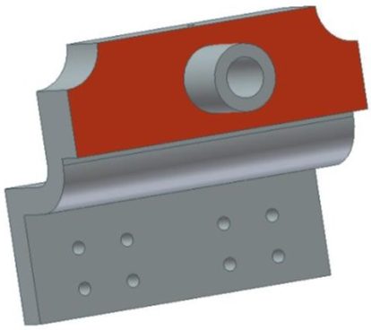
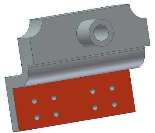
Using the next five figures below, change the colors of the machined faces shown to: Aluminum (Polished). (Figure Step 7A, 7B, 7C, 7D, and 7E)
Solid Model – Colored Faces
Solid Model – Colored Faces
Solid Model – Colored Faces
Solid Model – Colored Faces
Solid Model – Colored Faces
Lab Exercise 20-2
Time allowed: 60 minutes.
| Part Name: Inventor Lab 20-2 | Project: Inventor Course | Units: Inches |
| Template: N/A | Color: Blue Gray (Light) | Material: Cast Iron |
Step 1
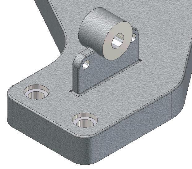
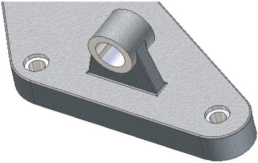
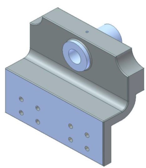
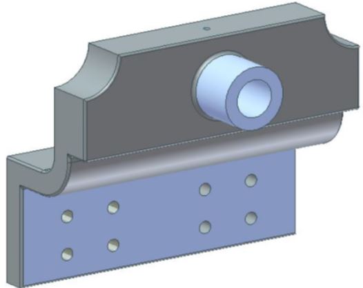
Open part: Inventor Lab 18-2.ipt that you created in Module 18. (Figure Step 1A and 1B)
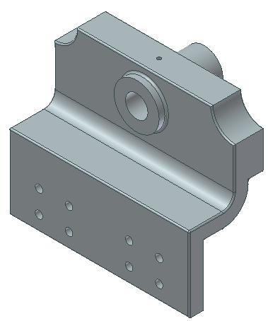
Solid Model – Home View
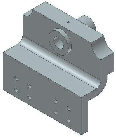
Solid Model – Without the Small Fillets
Step 2
Save the file as: Inventor Lab 20-2.
Step 3
Change the colour to: Blue Gray (Light)
Step 4
Move the End of Part Icon up above the small fillets as shown below. (Figure Step 4)
Step 5
Find the following with a precision of 5 decimal points. (Figure Step 5)
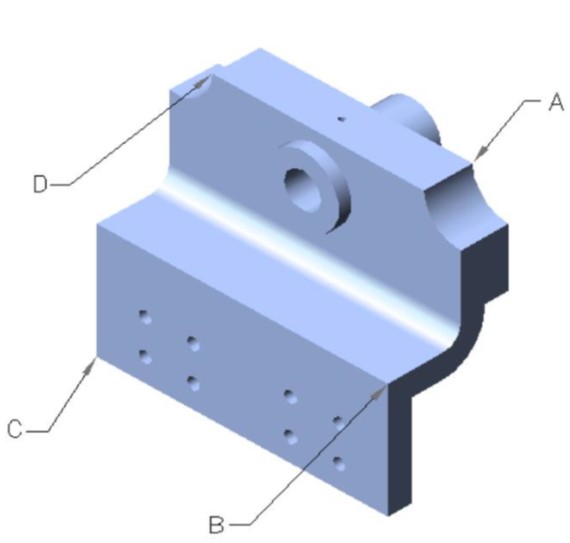
A The XYZ coordinates of corner A.
____________________________
B The distance from corner B to corner C.
____________________________
C The distance from corner B to corner D.
____________________________
D The area of the shaded area the figure. Do NOT include the area of the cylinder. (Figure Step 5D)
____________________________
E The perimeter of the shaded plane. (Figure Step 5E)
____________________________
F The area of the shaded area of the figure WITHOUT the eight small holes. (Figure Step 5F)
____________________________
Step 6
Move the End of Part icon back to bottom.
Step 7
Using the two figures, change the colors of the faces shown to: Blue Pastel. (Figure Step 7A and 7B)
Solid Model – Colored Faces
Solid Model – Colored Faces
Step 8
Set the material to: Cast Iron and find the following:
A The mass in pounds.
____________________________
B The mass in grams.
____________________________
Step 9
Save and close the part.
