Part 1
Module 3 Viewing the 2D Sketch and 3D Model
Learning Outcomes
When you have completed this module, you will be able to:
- Describe how to change the viewing position of the 2D sketch and the 3D model by zooming, panning, and orbiting.
- Apply the OPEN command to open existing Inventor files.
- Apply the ZOOM, ORBIT, ZOOM ALL, PAN, and HOME VIEW commands or use the wheel on the mouse to change the viewing position of the 2D sketch and 3D model.
Viewing the 2D Sketch and 3D Model
In Sketch mode, you are viewing and working on a two dimensional plane. In Model mode, you are viewing and working in three dimensions the same way the human eye see real objects. It is essential for you to be able to change the viewing position of the 2D sketch and the 3D model as required. This is done by zooming, panning, and orbiting to change the viewpoint of the 2D sketch and the 3D model.
Zooming
Zooming is the process of changing the viewable size of the sketch or model to make it appear either smaller or larger. It is an important tool for you and is used extensively in the drawing and modeling process. As it is zoomed, the size of the sketch or model not changed, Inventor is simply adjusting the distance the object is from your eyes making it appear larger or smaller. I wondered why the Frisbee was getting bigger, and then it struck me…
Panning
Panning is the process of moving the sketch or model around the Graphic window without actually physically moving it from its location in space. It is an important tool for you and is used extensively while working in Inventor.
Orbiting
Orbiting is the process of changing the orientation of the sketch or model in relation to your eyes. Rather then changing the orientation of your eyes, Inventor orbits the sketch or model and your eyes remain stationary. The model and sketch are not physically rotated or their orientation in space changed. Orbiting is used extensively when working in Inventor.
Home View
The Home view is important to you while working in Inventor. It is the viewing position of the sketch or model to a known isometric view. This view re-establishes your bearings to better visualize the sketch or model because you are viewing it in a known viewing position.
Inventor Command: OPEN
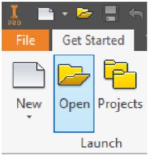
The OPEN button under the Get Started tab command is used to open an existing Inventor file.
Shortcut: CTRL+O
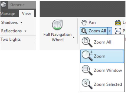
Inventor Command: ZOOM
The ZOOM command is used to zoom the sketch or model.
Shortcut: F3
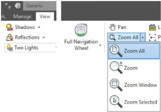
Inventor Command: ZOOM ALL
The ZOOM ALL command is used display the current sketch or model to fit inside the Graphic window.
Shortcut: HOME
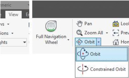
Inventor Command: ORBIT
The ORBIT command is used to orbit the sketch or model around the X, Y, or Z axes. The sketch or model can be orbited while another command is active.
Shortcut: F4
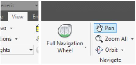
Inventor Command:PAN
The PAN command is used to move the sketch or model in the Graphic window.
Shortcut: F2
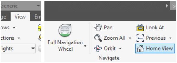
Inventor Command: HOME VIEW
The HOME VIEW command is used to display the sketch or model in the home view.
Shortcut: F6
WORK ALONG: Viewing the Model
Step 1
Start Inventor and check the current project. If required, set it to Inventor Course.
Step 2
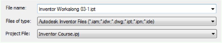
Click the Open icon. In the Open dialogue box, select the file:
Inventor Workalong 03-1.ipt . Note how the file name will appear in the File name: box as shown in the figure. (Figure Step 2)

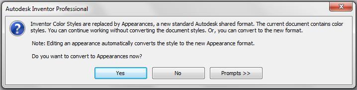
Step 3
If you are asked to convert the appearance, click Yes. (Figure Step 3).
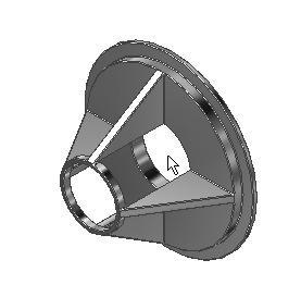
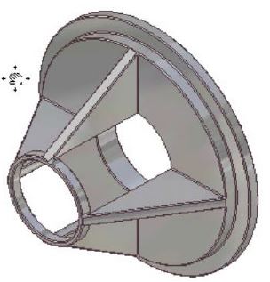
Step 4
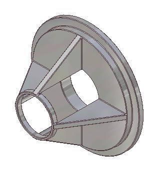
The part will open and display in Model mode and appear similar to the figure. (Figure Step 4).

Step 5
Move the cursor to approximately the centre of the solid model as shown in the figure. While keeping the cursor in the centre, rotate the mouse wheel back and forth. Note how the model appears larger and smaller. (Figure Step 5A and 5B)

USER TIP: When opening a file in Inventor, ensure that the Open File dialogue box is listing the correct file type(s). To list part files which have the extension .ipt , ensure that *.ipt file type is listed in the File of type: box as shown below. The * means that all files that have the extension .ipt.
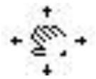
Step 6
Move the cursor near the model and press and hold the wheel down. A small Hand icon will replace the arrow cursor as shown in the figures. While the Hand icon is displayed, move the mouse to pan the model as shown. (Figure Step 6A, 6B, and 6C)

Step 7
Press F6 to return the model to its Home view. (Figure Step 7)

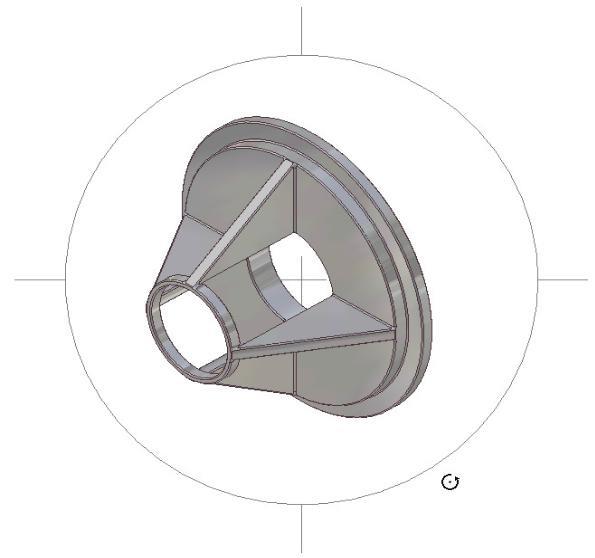
Step 8
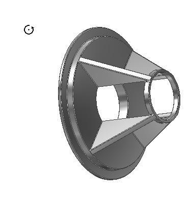
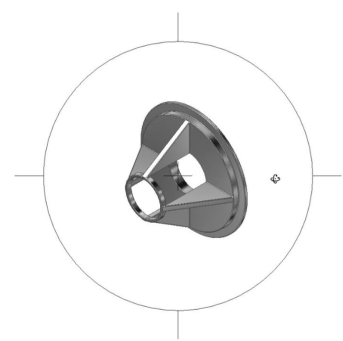
Press F4 and hold it down. While holding it down, move the cursor outside the orbit circle, as shown below. The cursor will change as shown in the figures. Press and hold down the left mouse button. While holding it down, move the mouse and the model will orbit. (Figures 8A, 8B, and 8C)

Step 9
Press F4 and hold it down. While holding it down, move the Graphic cursor somewhere inside the orbit circle. The icon will change in appearance as shown in the figures. Press the left mouse button and while holding it down, move the mouse. The model will orbit. (Figure Step 9A, 9B, and 9C)

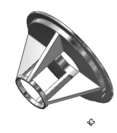
Step 10
Press F6 to return the model to its home view. (Figure Step 10)
Step 11
Close the part without saving it.
Key Principles
The Key Principles in Module 3
- It is essential for you to be able to change the viewing position of the 2D sketch and 3D This is done by zooming, panning, and orbiting to change viewpoint of the sketch or model.
- The HOME VIEW command is a very important command. Use it to change the viewing position of the 2D sketch or 3D model to a known isometric view. You can re-establish your bearings to better visualize the sketch or model.
- Use shortcut keys whenever possible to speed your production. Shortcut keys taught in this module are Home – Zoom All, F2 – Pan, F3 – Zoom, F4 – Orbit, and F6 – Home View.
