Learning Task 2
Sizing Gas Low Pressure and 2 psi Piping Systems
As was previously noted some of the capacity tables will include in their description “including fittings” and others will not. For all low pressure and 2 psig tables a 20% allowance has been included in the table length. Therefore the sizing procedure for these pressure ranges is very similar and they have been grouped together in this learning task.
Sizing Low Pressure Systems
Low pressure systems are systems in which the pressures do not exceed 0.5 Psig (14″ w.c.). The low pressure pipe sizing tables for natural gas are: A.1, A.2, A.8 and A.9. The low pressure pipe sizing tables for propane are: B.1 and B.6. All of these tables include fittings so a separate fitting allowance calculation is not required.
Once you have drawn the sketch and selected the correct table, you are ready to size the piping system.
The following is a summary of the steps required to size a piping system:
- Identify the gas (natural gas, propane, etc.).
- Identify the piping material (carbon steel pipe, copper tubing, or other).
- Identify the pressure system and the allowable pressure drop.
- Select the correct pipe sizing table.
- Calculate the gas load in Btu/h (or kW) on each section of pipe and list each load.
- Calculate the longest measured run in the system.
- Locate the appropriate code zone.
- Size each pipe in the system from the selected code zone.
Note: When branch lines are connected within 2' of the outlet of a meter or pressure regulator, this section is considered to be a manifold. All lines connected to the manifold are sized independent of the rest of the system, each with an individual longest measured run. A zero length is assumed for the manifold, and its size must be equal to or greater than the outlet size of the regulator.
Example 1 - Low Pressure Imperial
Refer to Figure 1 for an example of the sizing of a natural gas, low pressure, imperial system. Go through each step to size each pipe in the system.
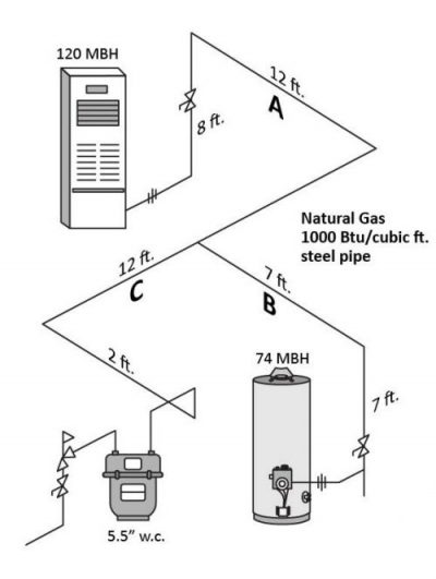
Pipe sizing example Figure 1 results
- Identify the type of gas; Natural gas
- Identify the type of pipe; Carbon steel pipe
- Identify the system operating pressure; The gas pressure being delivered through the gas meter is 5.5″ w.c.
- Select the pipe sizing table; From the information gathered in Steps 1, 2 and 3;, the appropriate table to be used is Table A.1 (Imperial). By using Table A.1, the pressure drop in the system should not exceed 0.5″ w.c.
- Calculate loads on each section of pipe in thousands of Btu’s per hour (MBH); On your sketch you will need to label the pipe so that you can make a list. When listing the loads, it is easier to start with the appliance that is furthest away from the meter and move back towards the meter, adding up the loads as you approach the meter.
- Pipe “A” = 120 MBH
- Pipe “B” = 74 MBH
- Pipe “C” = Pipe “A” + Pipe “B” = 194 MBH
- Calculate the longest measured run of the system, measuring from the meter to the most distant appliance; LMR =34 feet
- Select the code zone from the table that is equal to or greater than the LMR; CZ 40 feet
- Size each pipe in the system using the same code zone, selecting an equal of greater value then the pipe load being sized.
- Pipe “A”: 120 MBH = 3/4″
- Pipe “B”: 74 MBH = 1/2″
- Pipe “C”: 194 MBH = 1″
Example 2 - Low Pressure Metric
Refer to Figure 2 for an example of the sizing of a propane gas, low pressure, metric system. Go through each step to size each pipe in the system.
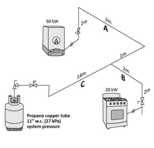
Pipe sizing example Figure 2 results
- Identify the type of gas; Propane gas
- Identify the type of pipe; Copper tube
- Identify the system operating pressure; The gas pressure being delivered from the twin stage propane regulator at the cylinder is 2.7 kPa (11″ w.c.)
- Select the pipe sizing table; From the information gathered in Steps 1, 2 and 3;, the appropriate table to be used is Table B.6 (Metric). By using Table B.6, the pressure drop in the system should not exceed 250 Pa.
- Calculate loads on each section of tubing in kilowatts (kW);
- Pipe “A” = 50 kW
- Pipe “B” = 20 kW
- Pipe “C” = Pipe “A” + Pipe “B” = 70 kW
- Calculate the longest measured run of the system, measuring from the propane system regulator to the most distant appliance; LMR =20 meters
- Select the code zone from the table that is equal to or greater than the LMR; CZ 21 meters
- Size each pipe in the system using the same code zone, selecting a equal of greater value then the pipe load being sized.
- Pipe “A”: 50 kW = 22 mm OD ([latex]\frac{7}{8}[/latex]″ OD)
- Pipe “B”: 20 kW = 16 mm OD ([latex]\frac{5}{8}[/latex]″ OD)
- Pipe “C”: 70 kW = 29 mm OD ([latex]1\frac{1}{8}[/latex]″ OD)
Sizing 2 psig (14 kPa) Piping Systems
With a 2 psig (14 kPa) supply pressure, you can design a smaller diameter piping system, which allows for additional cost savings. Residential 2 psig (14 kPa) systems are very common. Most gas appliances are not designed to accept inlet pressures of over 0.5 Psi (3.5 kPa), therefore, a line pressure regulator would be required before the appliance.
There are four 2 Psig (14 kPa) pipe sizing tables for natural gas, two allow for 1 psig (7 kPa) pressure drops and two allow for a 1.5 psig (10 kPa) pressure drop. If the 1.5 psig (10 kPA) tables are used, this would allow for smaller pipe sizes but a higher capacity regulator may be required due to the lower available operating inlet pressure to the regulator (0.5 psig/ 4 kPa). There are two 2 psig (14 kPa) pipe sizing tables for propane gas, both of these allow for a 1 psig (7 kPA) pressure drop.
For natural gas 2 psig (14 kPA) systems if the pressure drop is not specified the Gas Safety Authority recommends that a 1 psig (7 kPa) pressure drop is used in order to maximize the flow capacity of the line pressure regulator.
If the line Pressure regulator is located any appreciable distance (more than about 2 ft) before the inlet of the appliance, then a multiple pressure piping system is created, and each pressure zone will need to be sized separately with the appropriate table.
It is advisable to first size the low pressure zone (if required), and then to size the 2 Psig zone. The LMR for the low pressure zone will be measured from the 2 Psig line pressure regulator to the appliance. The LMR for the 2 Psig zone will be measured from the meter regulator to the 2 Psig line pressure regulator.
If the line pressure regulator is connected within 2 ft of the appliance then there is no need to use a piping capacity table to size the low pressure piping between the regulator and the appliance. The size is simply based on the larger of either; the line pressure regulator outlet or the appliance inlet connection.
Once you have drawn the sketch and selected the correct table or tables, you are ready to size the piping system.
First be sure to separately size any low pressure systems being supplied by the 2 psig system using there own LMR’s from each of there own 2 psig line Pressure regulators to the appliance.
The following is a summary of the steps required to size a 2 psig ( 14 kPa) piping system:
- Identify the gas (natural gas, propane, etc.).
- Identify the piping material (carbon steel pipe, copper tubing, or other).
- Identify the pressure system
- For natural gas select the allowable pressure drop, either 1 psig (7 kPa) pressure drop or 1.5 psig (10 kPa) pressure drop. If it is not specified choose 1 psig (7 kPa)
- Select the correct pipe sizing table.
- Calculate the gas load in Btu/h (or kW) on each section of pipe and list each load.
- Calculate the longest measured run in the 2 psig system. (measured from the meter regulator to the 2 Psig line pressure regulator).
- Locate the appropriate code zone.
- Size each pipe in the 2 psig system from the selected code zone.
Example 3 -2 psig (14 kPa)
Refer to Figure 3 for an example of the sizing of a 2 psig and 7″ w.c. system. Go through each step to size each pipe in each separate system.
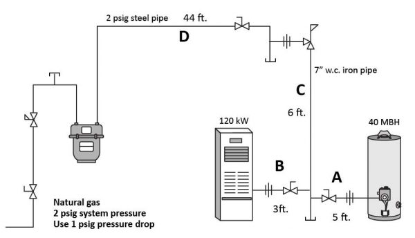

Pipe sizing example Figure 3 results
Sizing of low pressure system first:
- Identify the type of gas; Natural gas
- Identify the type of pipe; Carbon steel pipe
- Identify the system operating pressure; The gas pressure being delivered from the line pressure regulator is 7″ w.c.
- Select the pipe sizing table; From the information gathered in Steps 1, 2 and 3;, the appropriate table to be used is Table A.2 (a) Imperia]. By using Table A.2 (a), the pressure drop in the system should not exceed 1″ w.c.
- Calculate loads on each section of piping in MBH;
- Pipe “A” = 40 MBH
- Pipe “B” = 120 MBH
- Pipe “C” = Pipe “A” + Pipe “B” = 160 MBH
- Calculate the longest measured run of the system, measuring from the line pressure regulator to the most distant appliance; LMR =11 feet
- Select the code zone from the table that is equal to or greater than the LMR; CZ 20 feet
- Size each pipe in the system using the same code zone, selecting a equal of greater value then the pipe load being sized.
- Pipe “A”: 40 MBH = ½″ NPS
- Pipe “B”: 120 MBH = ½″ NPS
- Pipe “C”: 160 MBH = ¾″ NPS
Sizing of 2 psig pressure system:
- Identify the type of gas; Natural gas
- Identify the type of pipe; Carbon steel pipe
- Identify the system operating pressure and pressure drop for natural gas; 2 psig meter supply pressure with an allowable system pressure drop of 1 psig.
- Select the pipe sizing table; From the information gathered in Steps 1, 2 and 3;, the appropriate table to be used is Table A.3 (a) Imperia]. By using Table A.3 (a), the pressure drop in the system should not exceed 1 psig.
- Calculate loads on each section of 2 psig piping in MBH;
- Pipe “D” = 160 MBH
- Calculate the longest measured run of the system, measuring from the meter to the line pressure regulator; LMR =44 feet
- Select the code zone from the table that is equal to or greater than the LMR; CZ 50 feet
- Size each pipe in the 2 psig system using the same code zone, selecting a equal of greater value then the pipe load being sized.
- Pipe “D”: 160 MBH = ½″ NPS
Notice that the line pressure regulator will have a smaller size inlet pipe than outlet pipe this not uncommon due to the different system pressures. The selected regulator will typically have the same connection size on the inlet and outlet therefore the piping will need to be adapted immediately before or after the regulator, as needed, to the proper pipe size.
When a branch line is connected within 2' of the outlet of a meter or pressure regulator, this section is considered to be a manifold. All lines connected to the manifold are sized independent of the rest of the system, each with an individual longest measured run and appropriate code zone. A zero length is assumed for the manifold and in fact this manifold section could end up being smaller than a branch that might be added, as described in code clause 6.6.2. Think of it as though the runs from the manifold are connecting directly into the gas source (regulator) therefore there is no significant pressure loss in the area immediately downstream of the meter or line pressure regulators as long as the manifold size is no smaller than the regulator outlet size.
Now complete Self-Test 2 and check your answers.
Self-Test 2
Self-Test 2
- Size the drawing in Figure 4 and show all calculations.
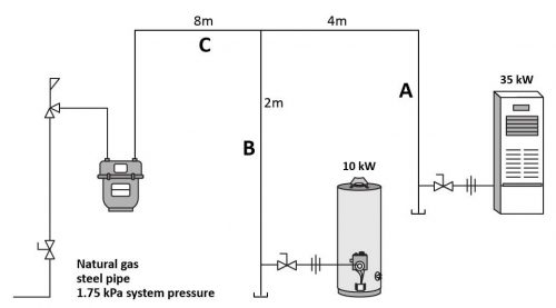
Figure 4 Type of Gas Piping Material System Pressure Table Used Table Allowable Pressure Drop Longest Measured Run (LMR) Code Zone (CZ) Pipe Letter Pipe Load Pipe Size A B C - Size the drawing in Figure 5 and show all calculations.
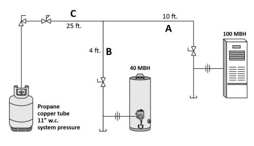
Figure 5 Type of Gas Piping Material System Pressure Table Used Table Allowable Pressure Drop Longest Measured Run (LMR) Code Zone (CZ) Pipe Letter Pipe Load Pipe Size A B C - Size the drawing in Figure 6 and show all calculations.
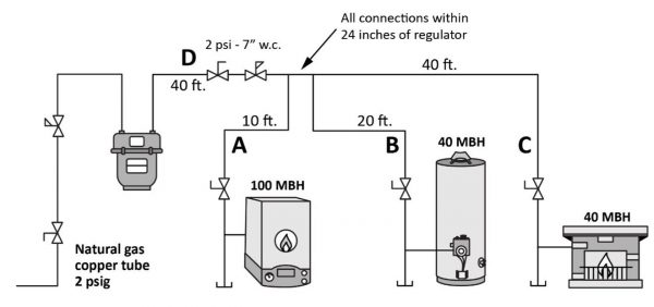
Figure 6 Type of Gas Natural Gas - Low Pressure Systems Natural Gas - High Pressure Systems Piping Material System Pressure Table Used Table Allowable Pressure Drop 1 psig Longest Measured Run (LMR) A = B =
C =
Code Zone (CZ) A = B =
C =
Pipe Letter Pipe Load Pipe Size A B C D
Check your answers using the Self-Test Answer Keys in Appendix 1.
Media Attributions
- Figure 1 "Low pressure pipe sizing (Imperial) example" by Camosun College is licensed under a CC BY 4.0 licence.
- Figure 2 "Low pressure pipe sizing (Metric) example" by Camosun College is licensed under a CC BY 4.0 licence.
- Figure 3 "Pipe sizing example for 2 psig system" by Camosun College is licensed under a CC BY 4.0 licence.
- Figure 4 by Camosun College is licensed under a CC BY 4.0 licence.
- Figure 5 by Camosun College is licensed under a CC BY 4.0 licence.
- Figure 6 by Camosun College is licensed under a CC BY 4.0 licence.
