Learning Task 1
Creating Gas Piping Design Documents
A drawing of the whole gas piping system allows you to identify and locate important system components and create a materials list. Knowing the following details will also help you properly size the piping system.
- Gas supply – The gas supply may be a meter installed by a local utility company for natural gas or propane. In other cases, propane may be supplied from a storage container.
- System pressure – For residential meter sets the gas utility will supply two options for outlet pressures, either a 2 psig of a 7″ WC. In many jurisdictions the only meter pressure available for a residential service is now 2 psig.
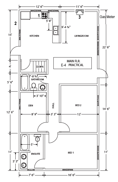
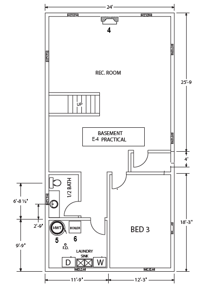
- Appliance location – The appliance’s location is usually fixed by the building design and not the gas fitter. The architectural drawing will be needed to identify the locations.
- Appliance inputs – The appliance input, determines the amount of gas required by the appliance. Each appliance’s input is determined by the manufacturer, then stamped on a rating plate, and permanently affixed to the equipment. At the design stage the actual gas appliance is not usually available, so you will need to rely upon the equipment manufactures specifications
- Piping route – You must determine the best piping route. The best piping route is usually the one that uses the least amount of pipe, fittings, and valves.
- Valves and related equipment – Every piping system requires valves and other equipment such as regulators. You must know where this equipment will be located before sizing the piping system.
Create Plans and Isometric Drawings of Gas Piping Systems
The gas piping plan is a two-dimensional plan view drawing showing the gas piping system. It is generated from the architectural floor plan showing the types and locations of the gas appliances. The piping plan describes the location, sizes and types of all piping and fittings used in the system. The horizontal piping is drawn to scale, but due to the two-dimensional properties of the drawing, only the locations of all vertical pipes are shown.
Sketching a Plan View
You may choose to draw the orthographic piping plan on the house plan, or you may want to use a separate sheet of paper. The first step in creating an orthographic piping plan is to determine the locations of any gas appliances and their supply connection location.
At this point the gas appliance is not usually available so you will need to rely upon the equipment manufactures specifications for the piping connection details. It is very important to note where the gas meter is located, as this will be the design ending point. You can then create a network of lines that tie-in all of the gas appliances, working back from the appliances toward the meter. The piping will often run in the ceiling joists and feed both upper and lower floor appliances though the floors and walls.
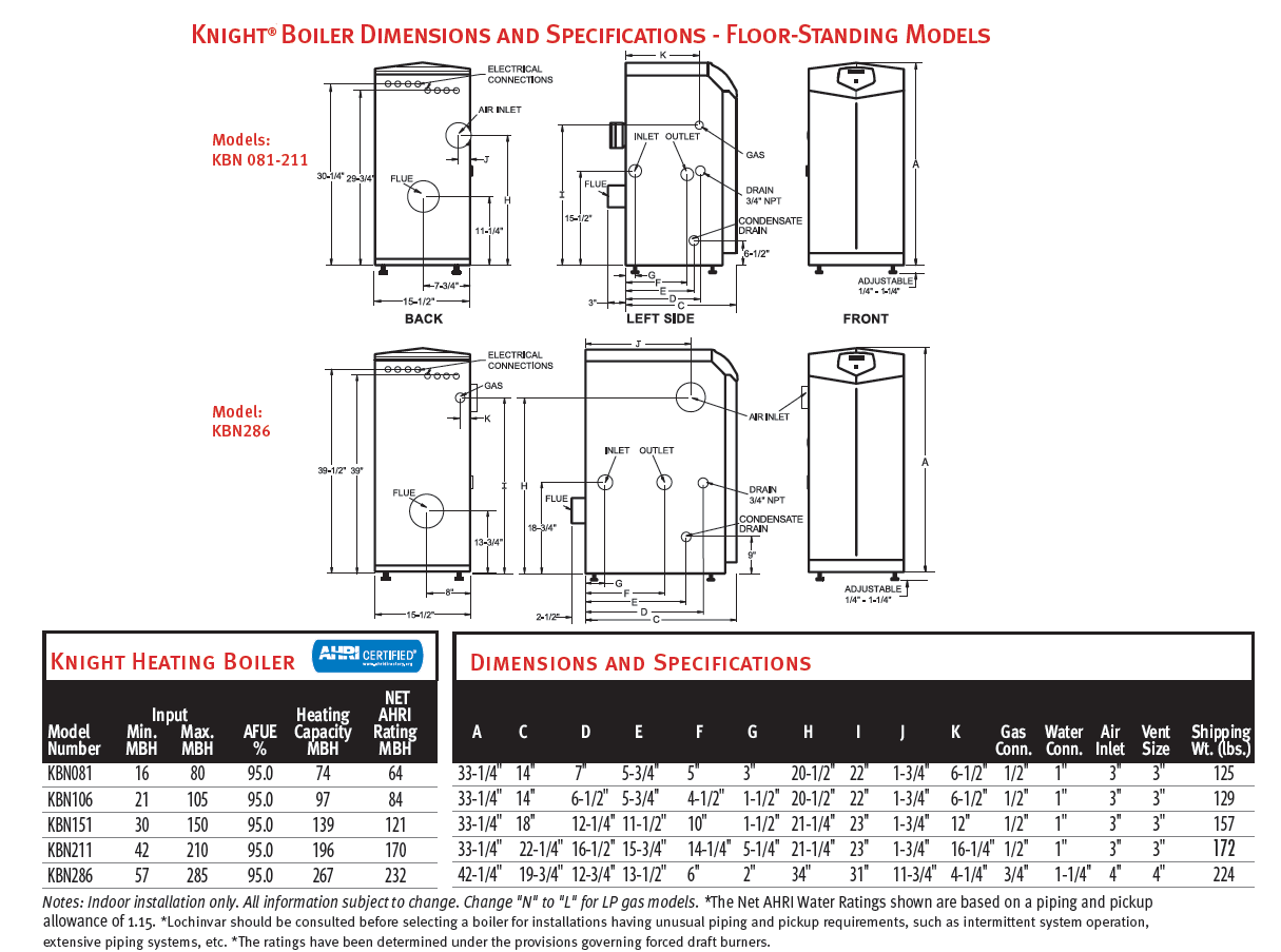
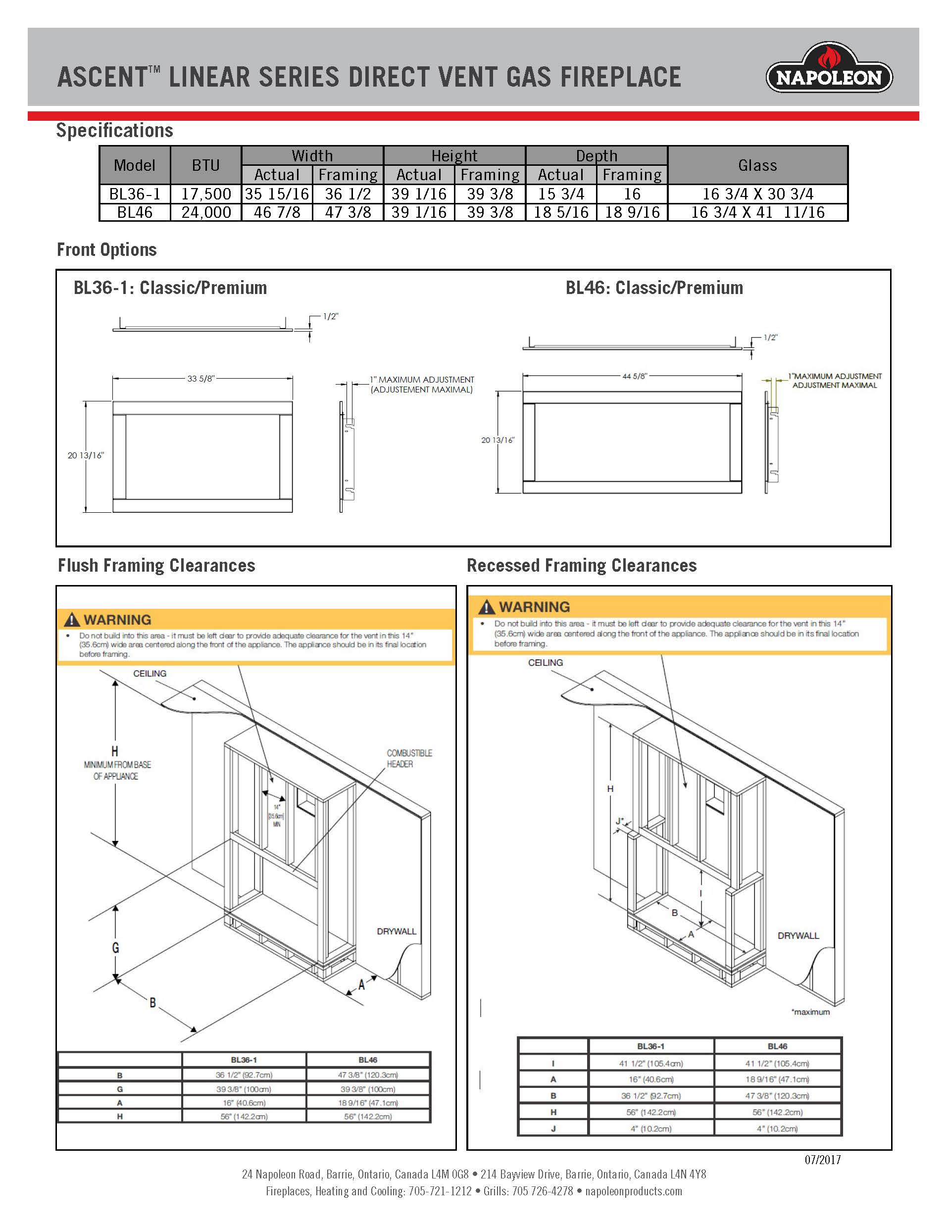
Appliance Specifications
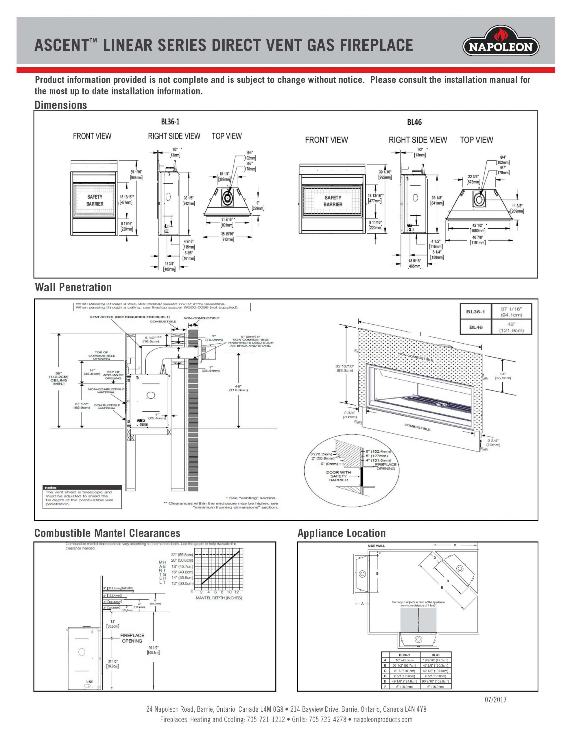
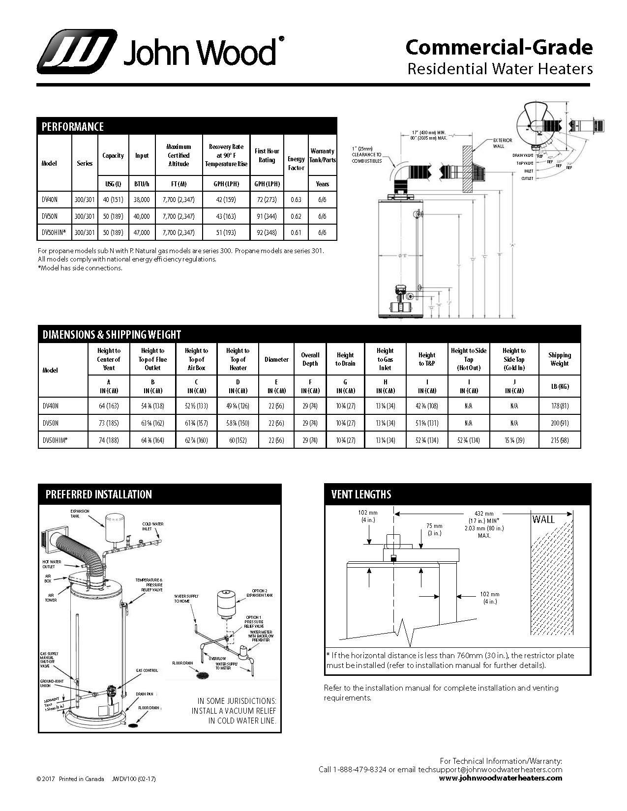
Once the appliance locations have been established on the plan drawing, the next step is to reference the appliance manufacturer’s specifications (figure 1) to determine:
- Appliance input
- Connection location, type and size
Sketching Residential Isometric Piping Drawings
Isometric drawings are generated from the information found on the orthographic plan and elevation views when available. Unlike orthographic piping plans, isometrics allow the system to be drawn in a manner by which the length, width and height are shown in a single view. This allows for a more complete view of the system. Usually, piping isometrics are drawn on sheets pre-printed with lines drawn vertically and at 30° to the horizontal. The symbols that represent fittings and valves are modified to adapt to the isometric grid. Isometrics are the most important drawings for mechanical contractors during the rough-in portion of a project.
Material Take-Off
To stay organized, it is advisable when doing a material take-off, to start at the most remote appliance and work toward the gas supply to avoid missing or duplicating material requirements. Because there is so much material information that you take off the drawings, it is best to use some kind of form to keep all of the information organized. The pipe and fittings should be arranged according to size and type (Figure 2). Most gas piping systems that are constructed use more fittings than what was estimated in the take-off. These extra fittings are largely elbows used in getting around obstructions. An allowance should be made for extra fittings that are over and above the total in the estimate. The actual percentage will be refined as you become more experienced, but it will be in the area of 5% of the total counted.
| Quantity | Size | Fitting Name |
|---|---|---|
A relatively straightforward gas appliance schedule (figure 3) can be created that references a numbered location on the plan drawing. The appliance schedule will also give enough make and model information to enable you to refer to the appropriate equipment specification.
| Ref. # | Equipment Type | Make and Model |
|---|---|---|
| 01 | Force Air Furnace | American Standard – S9V2- |
| 02 | Gas Fireplace | Napoleon – Ascent Linear 36 |
| 03 | Storage Water Heater | Rheem – G50-40N |
Practical Competency Design a Residential Gas Piping System
- Create a plan view of the residential piping system from an architectural drawing
- Refer to the architectural drawing on the following page.
- Use the drawing to create a plan view drawing of the gas piping system.
- Scale the drawing as per your instructor’s directions.
- Equipment
- architectural drawing supplied
- drawing instruments
- appliance specification’s supplied in flowing pages
- Create an sized isometric projection from the piping plan view
- Equipment
- isometric grid paper
- orthographic DWV plan from step #1
- B 149.1 Code book
- Equipment
- Create material list from the piping isometric
- Equipment
- Isometric drawing from step #2
- Equipment
Evaluation Criteria
Your instructor will evaluate your work using the following criteria:
- Plan view routing is efficient.
- Isometric drawing is proportional to plan view.
- Appliance loads are shown on drawings
- Pipes are correctly sized as per the B149.1 Gas Code
- Material list included all pipe, fittings, valves and connectors required to complete the installation.
Appendix 1 Project Floor Plans
| Ref. # | Equipment type | Make and model |
|---|---|---|
| 01 | Gas Fireplace | Napoleon – Ascent Linear BL36-1 |
| 02 | Gas Fireplace | Napoleon – Ascent Linear BL 46 |
| 03 | Storage Water Heater | John Wood – DV50N 300 |
| 04 | Hydronic Boiler | Knight – KBN 106 |
Appendix 1 Project Equipment Specifications
Media Attributions
- Figure 1 Boiler product summary sheet © Lockinvar. Used with permission.
- “Project floor plans” were taken from ITA Plumber Level 2 Module C2 by Trades Training BC with modifications: Fireplaces added, Gas meter added, appliance numbers added, title box changed. CC BY 4.0 licence.
- Accent™ Linear Series Direct Vent Gas Fireplace © Napoleon. Used with permission.
- John Wood Commercial Grade Residential Water Heaters © John Wood. Used with permission.
