Learning Task 2
Describe Conductor Installation
Boxes and Enclosures
The Canadian Electrical Code (CEC) dictates that no wiring splices are allowed outside of an approved enclosure. Any standard outlet box, switch box, or light fixture box (known as device boxes) can serve as an approved enclosure, but where a wiring splice needs to occur in other locations along the circuit, the approved enclosure is usually called a junction box. A junction box is simply a standard electrical box that is mounted securely to framing or the structure, and containing the connection (splice) of two or more conductors.
Cables are secured to the box with cable clamps (or conduit connectors if the circuit includes conduit) and the box must have a removable cover to create a complete enclosure. Junction box covers must remain accessible; they cannot be covered with drywall or other surface material.
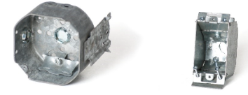
Examples of common device boxes are shown below.
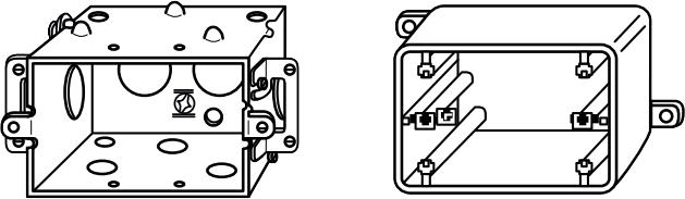
If using metal conduit to run wiring to the electrical box, then a metal box is required, firstly to anchor the conduit and secondly because the conduit and metal box system itself may be used to ground the system. If using non-metallic sheathed cable (NMSC), such as “Loomex” NMD-90, then you can use either plastic boxes or metal boxes, as long as the cable is secured to the box with an appropriate cable clamp.
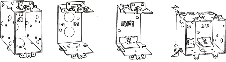
Single light fixture switches and outlet receptacles typically fit into standard rectangular boxes, also known as “single-gang” or “one-gang” boxes. They are generally 2 x 3 inches in size, with depths ranging from 1 1/2 inches to 3 1/2 inches. Some boxes are “gang-able”—with detachable sides that can be removed so the boxes can be linked together to form larger boxes for holding two, three or more devices side-by-side.
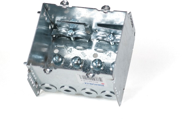
If the box doesn’t have an internally-installed means of securing the cable to the box, as shown in the image of the 2-gang box above, the box will need to have a “box entry fitting” or cable connector attached through a knockout on the box wall.
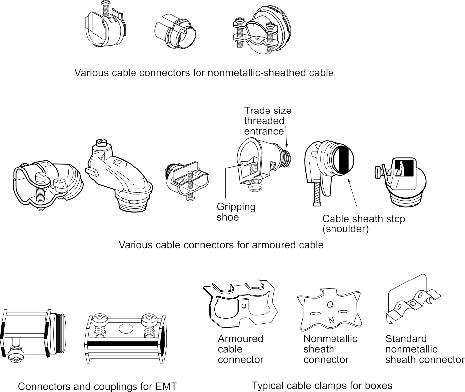
This entry fitting is normally secured to the box by a threaded connection, and the cable is held to it by a clamp with screws, as seen in some of the images above. If armoured cable is used, box entry fittings appropriate for that cable must be used.
Wire and Protection
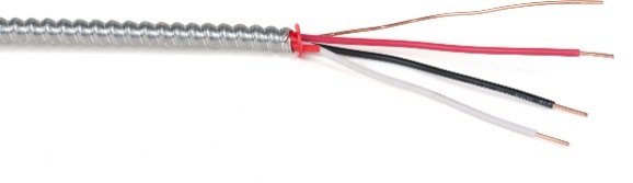
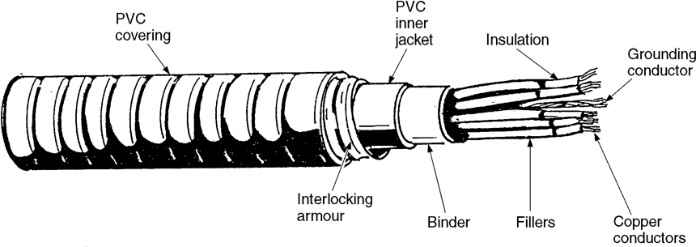
There are many varieties of electrical wire available. Section 4 of the CEC states that any exposed wiring that is within 1.5m (5 feet) of the floor has to be protected from damage. This can be done in a few different ways, one of which is by using armoured cable, sometimes referred to as “BX” or “Tech” cable. Teck cable has more layers of material inside it than does BX, as well as a waterproof vinyl coating and so is able to be used in more areas than BX can. BX is simply a hollow flexible helix of metal with insulated conductors and a bare bonding wire supplied inside it.
Cables and insulated wires can also be protected by being run through tubing made of plastic or metal or through Schedule 40 pipe. All these are generally referred to as conduit, although the term only correctly applies to the Sch 40 material which uses threaded connections.
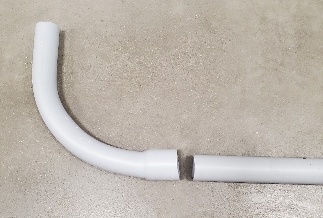
PVC conduit is solvent-welded together, and drastic changes in direction are made through the use of an elbow sometimes called a “sweep”. These are long-radius 90° elbows that allow wires to be pulled through them more easily than if they are of the short-turn variety. Threaded PVC adapters are used for attaching PVC conduit to boxes.
PVC conduit also comes in lengths or rolls of flexible tube which can save the installer time and money by not requiring elbows for changes of direction. Couplings facilitate tube-to-tube connections and threaded adapters connect tube-to-boxes.
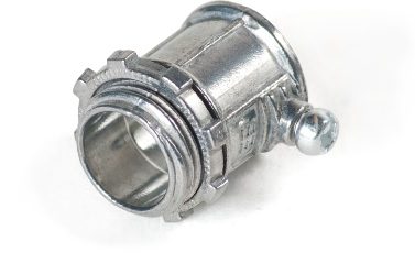
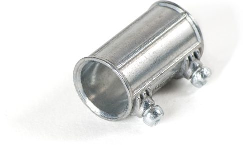
EMT is joined using fittings with set screws as seen below. Bends in EMT can be made with tubing benders or through the use of metal conduit elbows and set-screw couplings.
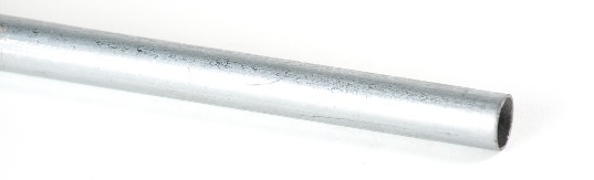
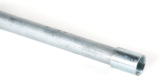
Rigid metal conduit is galvanized Schedule 40 pipe and is joined using galvanized threaded fittings.
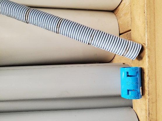
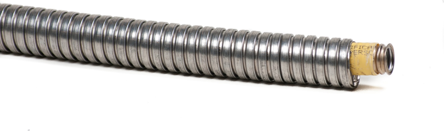
Flexible metal conduit is similar to BX but without the wires placed inside it by the manufacturer. Like the flexible plastic conduit, wires are pulled into it after it is installed between boxes (“pull points”). The image below shows a flexible gas line installed within flexible metal conduit.
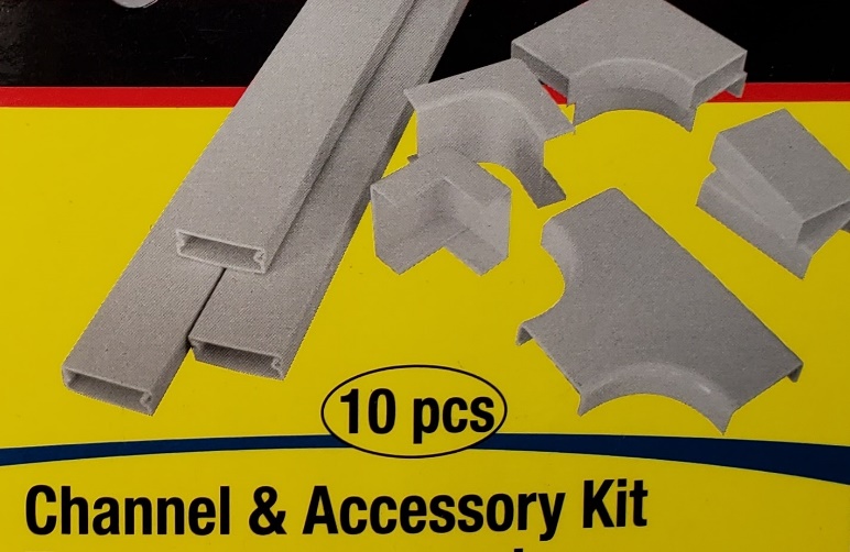
In the electrical world, a “raceway” is essentially any rigid enclosed or semi-enclosed channel that protects, routes and hides cables and wires. A surface raceway is an excellent choice for concealing and protecting wires between components in a mechanical room. A plastic track is attached to a horizontal or vertical surface, into which wires and cables can be laid or fastened. A plastic cover snaps over the assembly, creating a neat, finished product while also allowing for future wires to be installed.
Separation of Circuits
Sections 12 and 16 of the CEC impose restrictions on the installation of Class I and Class II circuits (limited power circuits) within the same raceway with those supplying circuits of unlimited power. Hydronics controls circuits are predominantly Class II circuits, with power output limited to 100 VA (Watts). To avoid issues of voltage and current transference via electromagnetic induction, as well as to satisfy Code requirements, it is always best to keep line voltage wiring separated from low voltage (24VAC) wiring, even if they are to be connected to the same piece of equipment. Avoid pulling low voltage wire or cable through any holes in structural members that have line voltage wires or cables in them. A good rule of thumb is to keep at least 2 inches of separation between low and line voltage wiring.
Box and Conduit Fill Limits
The physical size of boxes and conduit has to be appropriate for the number and type of conductors within them. Rules found in 12-3034 and 12-3036 of the CEC impose limits on the number of conductors that can be installed in boxes and conduit. The determining factors are many, and include internal volume of the box, the number of conductors, conductor gauge, number of wire connectors, and number and size of devices installed within the box. As such, the interpretations of those rules involve much study. Before attempting to install a circuit, consult the applicable Code rules and solicit the opinion and expertise of a qualified electrician if unsure.
Media Attributions
- Figure 1 Metal (left) and plastic (right) device boxes by ITA is licensed under a CC BY-NC-SA licence.
- Figure 2 Device and junction boxes by ITA is licensed under a CC BY-NC-SA licence.
- Figure 3 “Gang-able” boxes by ITA is licensed under a CC BY-NC-SA licence.
- Figure 4 2-gang device box with integral cable clamps by ITA is licensed under a CC BY-NC-SA licence.
- Figure 5 Various cable-to-box fittings by ITA is licensed under a CC BY-NC-SA licence.
- Figure 6 “BX” armoured cables by ITA is licensed under a CC BY-NC-SA licence.
- Figure 7 “Teck” armoured cables by ITA is licensed under a CC BY-NC-SA licence.
- Figure 8 PVC conduit and 90-degree elbow or “sweep” by ITA is licensed under a CC BY-NC-SA licence.
- Figure 9 Flexible PVC conduit and coupling by ITA is licensed under a CC BY-NC-SA licence.
- Figure 10 Thin-walled electrical metallic tubing (EMT) by ITA is licensed under a CC BY-NC-SA licence.
- Figure 11 EMT box entry fitting by ITA is licensed under a CC BY-NC-SA licence.
- Figure 12 Coupling by ITA is licensed under a CC BY-NC-SA licence.
- Figure 13 Rigid metal conduit by ITA is licensed under a CC BY-NC-SA licence.
- Figure 14 Flexible metal conduit protecting a CSST gas line by ITA is licensed under a CC BY-NC-SA licence.
- Figure 15 Surface-mounted plastic channel by ITA is licensed under a CC BY-NC-SA licence.
