Learning Task 1
Describe Wiring Components
If the designer has also produced a schematic or a ladder diagram for the wiring and controls, all that is left is the physical installation of the electrical components. This is where installers have had, and continue to have, issues. Those issues revolve around the parts, pieces and installation techniques required by the installer to ensure that this part of the system is completed properly. We’ll look at some of the things that come into play when wiring hydronic systems.
“Field Wiring”
The wiring that we, the installers, are responsible for is commonly shown on manufacturers’ literature and labeled as “field wiring”. This is any wiring that is not pre-installed on the equipment at the factory. In a forced air furnace installation, the field wiring is usually limited to the wiring for the thermostat and the connection of the line voltage power supply. There is much more field wiring needed for hot water heating systems. The legal ability for pipe trades personnel to perform any field wiring of a hydronic heating system, regardless of voltage, falls under a Gasfitter “A” or “B” Certificate of Qualification, as long as the fitter is working under a gas contractor’s license, an installation permit has been obtained and the heat source is gas-fired. Most in the hydronics industry would agree that a plumber/gasfitter, rather than an electrician, should logically be the person to perform this work due to the knowledge and understanding of the components involved in hydronics and the “sequence of operation” for our gas systems. That having been stated, let’s turn our attention to the physical aspects of the wiring installation for our systems.
Wire Versus Cable
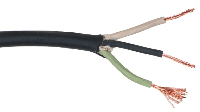
The terms “conductor” and “wire” are synonymous, meaning they are referred to as the same when describing the actual component that will carry current between two points in a circuit. Wire is made of either copper or aluminum, with copper being the material of choice. Solid wire is used in permanent installations that won’t be subjected to much movement or vibration in their life. Stranded wire is used in extension cords for portable equipment where there will be much movement and portability in use. In either case, the wire insulation on each conductor keeps the wires from unwanted contact with each other or the equipment around it.
While extension cord can be allowable for limited use in situations where equipment must be moved often for cleaning or routine maintenance, it is not acceptable for use in permanent installations of fixed equipment.
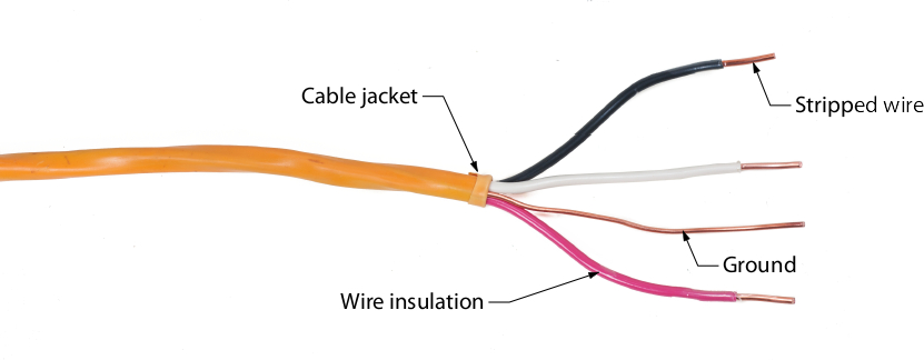
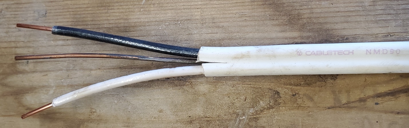
Cables consist of individual insulated conductors, contained within a jacket or sheath. The wire insulation is normally either rubber or some variety of plastic. The sheath could be a vinyl material, such as in an NMD90 cable, as seen below, or could be more robust so as to protect the wire from damage, as in the armoured cable also shown below.
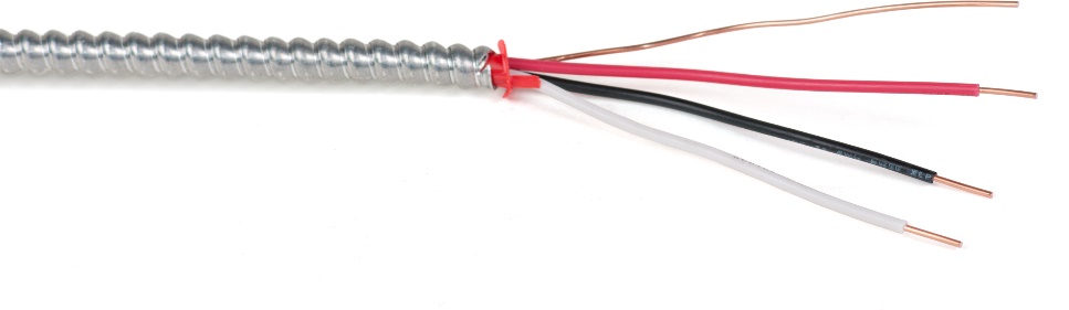
Some of the metal sheath of armoured cable must be removed when making wire connections. To do so, first bend the cable until the armour begins to pop open. Next take a saw blade or side cutters and cut through the remaining armour avoiding coming into contact with the conductors. Once the armor is cut through, remove the armor sheath to expose the conductors. A split plastic bushing should be pushed into the end of the metal sheath to protect the issuing conductors from abrasion.
Media Attributions
- Figure 1 Solid-wire non-metallic sheathed cable by ITA is licensed under a CC BY-NC-SA licence.
- Figure 2 Stranded-wire extension cord by ITA is licensed under a CC BY-NC-SA licence.
- Figure 3 2-conductor non-metallic sheathed cable (NMD90) by ITA is licensed under a CC BY-NC-SA licence.
- Figure 4 3-conductor armoured cable by ITA is licensed under a CC BY-NC-SA licence.
