Learning Task 3
Describe Wire Termination
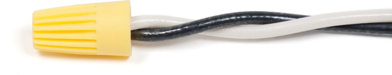
Twist-on Connections
Conductors can be joined together by a number of means, the most common being via solderless wire connectors, also known as “wire nuts” or “twist-on” connectors as shown below.
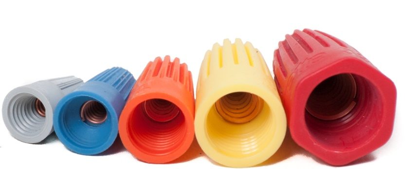
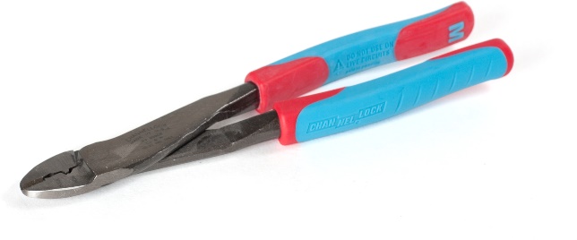
The devices shown above are most commonly referred to as “marrettes”, again reflecting our industry’s tendency to name tools or components based on their inventor or original patent holder, such as we do with “Channellock” pliers or a “Crescent” wrench.
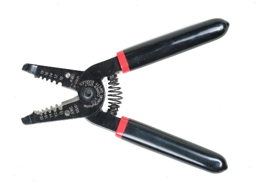
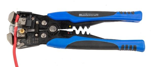
To properly join two or more wires using a wire nut, the ends of the conductors must first be stripped of the insulation covering them, using wire strippers.
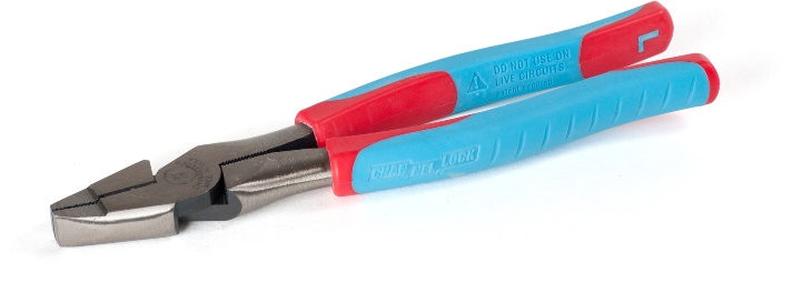
There should be approximately ¾″ to 1″ of bare wire exposed. Next, grip the two or more wires into a cluster, with the ends of the insulation, rather than the bare wire ends, lined up together. Using a pair of lineman pliers or a specialty tool for the purpose, twist the bare wires together into a tightly-wound assembly.
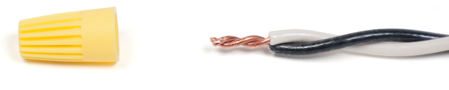
Using the cutting jaws of the pliers or a pair of side cutters, cut the wound end of the wires off so that there is approximately [latex]\dfrac{5}{8}[/latex]″ – ¾″ of bare wires left showing. Next, select a twist-on connector that is appropriate for the number and gauge of wires being joined within it. Manufacturers sometimes publish such information on the packaging for the connectors.
Twist the wire nut clockwise onto the wire cluster until hand-tight. Then, using pliers, give the wire nut another ¼ to ½ turn. This ensures that the connector is appropriately tight.
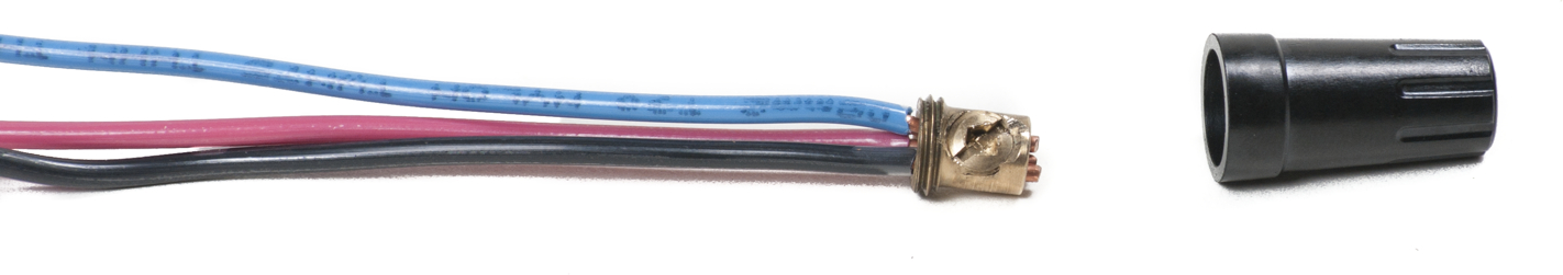
Another type of wire connector uses what looks to be a marrette-type of housing over a set-screw connector, as shown below. The wires are inserted into the brass barrel and the set screw is tightened down onto them. The cap is then screwed onto the barrel snugly to complete the connection.
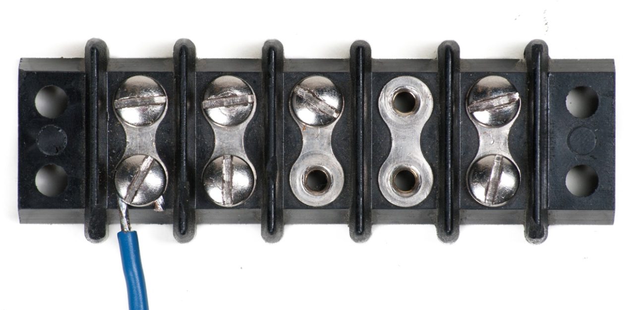
If wires are smaller in diameter (higher in gauge number) than #14AWG, they should be joined by lug-type connections. Even a slight scoring from a knife when stripping the insulation on 18AWG solid copper conductors can result in the small-diameter wire breaking when being twisted together under a marrette. The image below shows a terminal strip that can be helpful for connecting smaller-gauge wires. The end of the wire is bared and either hooked under a terminal screw, as shown, or pushed into a slot that has a set screw to hold it there.
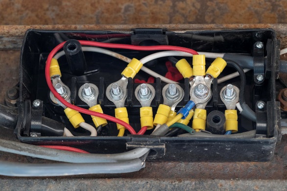
Terminal strips come in various lengths, are often gang-able and are also available within a junction box where there are threaded posts on which to make multiple connections, as seen in the image below.
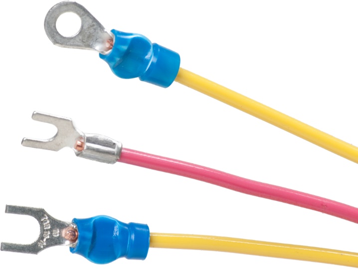
Wires can also be connected together by crimping. The shoulders of crimp fittings can either be insulated or bare and they come in a wide variety of sizes and configurations. A dedicated crimping tool or a combination stripper/crimper is used to secure the terminal fitting to the wire end.
The image below shows crimped wire terminals (ends). Only about [latex]\dfrac{1}{4}[/latex]″ to [latex]\dfrac{3}{8}[/latex]″ of the conductor has to be bared when using crimp connectors. The bared wire end is pushed into the opening so that the insulation butts up against the shoulder of the connector. If the connector is too large for the wire gauge, the wire can be pushed too far into the terminal, resulting in a situation where the insulation is sandwiched between the wire and the inside of the connector, with little or no contact between wire and connector. Crimp fittings are colour coded to indicate the size wire they are meant to be used with.
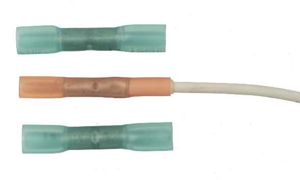
Heat shrink sleeves can be used to insulate and protect a crimped connection. Some heat shrinks have the ability to seal the connection from water, such as in a well pump installation.
The CEC also allows soldered wire connections for power conductors (hots and neutrals) but not for bonding conductors. A bonding conductor is usually bare or covered with green insulation if in an extension cord. Bonding conductors tie together all the metal components of a circuit that are never meant to be live so that, in the event of a “short” between a hot wire and a metal component of the circuit, the breaker will trip and any electrocution hazard is nullified. If too much current passes through a soldered “hot” connection without tripping the overcurrent device (breaker or fuse), the solder will melt and the wires will likely become disconnected, which in turn should deaden the circuit. If that were to happen to a soldered bonding conductor, the ground connection would be lost, the breaker or fuse could be unaffected and an electrocution hazard could still exist.
Any soldered connection must be made over with a heat shrink or electrician’s tape so that it has at least the same level of insulation as the wire.
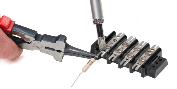
When making soldered wire connections, make sure to not overheat any of the components. Using a heat sink, such as a pair of pliers to hold the wire very near the soldering point, as shown in the image above, helps to dissipate unwanted heat.
Now complete the Self-Test 5.
Self-Test 5
Self-Test 5
- Complete the following statement: “Field wiring is .”
- Wiring done on a rural property
- Wiring that is not factory installed
- Wiring associated with a magnetic field
- Wiring provided by Field and Associates
- What is the difference between “wire” and “cable”?
- Cable is constructed of steel
- Wire is constructed of aluminum
- Cable consists of individual wires
- Wire consists of individual cables
- What is the purpose of a split plastic bushing when used with armoured cable?
- To prevent abrasion of the wire insulation
- To change between two cable diameters
- To help build up insulation thickness
- To change from steel to plastic
- Within the context of the explanations in this guide, what does “CEC” stand for?
- Canadian Energy Conglomerates
- Cable Energizing Configuration
- Constant Energy Connection
- Canadian Electrical Code
- What type of box must be used with metal conduit?
- Metal
- Plastic
- Concealed
- Either metal or plastic
- If a device box can be dismantled and made larger, it is said to be .
- Gang-able
- Adaptable
- Versatile
- Useable
- How are box entry fittings attached to boxes?
- By spot welding
- Through the cover plate
- Through the rear of the box
- Through knockouts on the box wall
- According to the CEC, exposed conductors must be protected from damage if within of the floor.
- 1.5 m
- 2.6 m
- 3.0 m
- 5.0 m
- What is the difference between “BX” and “Teck” cable?
- “BX” is waterproof; “Teck” isn’t
- “Teck” is waterproof; “BX” isn’t
- “BX” has flexible armour; “Teck” doesn’t
- “Teck” has flexible armour; “BX” doesn’t
- What is used to connect PVC conduit to a box?
- A sweep
- A threaded adapter
- A swaged-end connector
- A solvent-welded coupling
- What type of material is rigid metal conduit?
- PVC plastic
- Copper tubing
- Thin-walled metal tubing
- Galvanized Schedule 40 pipe
- What is any rigid enclosed or semi-enclosed channel that protects, routes and hides cables and wires known as?
- A conduit
- A pathway
- A raceway
- A rigid channel
- What is the power output limitation for a Class II circuit?
- 100 Amps
- 100 Ohms
- 100 Volts
- 100 Watts
- What is the general rule regarding separation distance between low voltage and line voltage conductors that are in close proximity to each other?
- Maintain at least 2 inches physical distance between them
- They cannot be in the same room together
- There is no minimum separation required
- Maintain at least 2 meters of separation
- A “marrette” is an example of a of wire connector.
- Soldered type
- Solderless type
- Set-screw type
- Threaded adapter type
- How much length of tightly-twisted bare wire ends should there be under a wire nut connection?
- [latex]\dfrac{1}{8}[/latex]″ – [latex]\dfrac{1}{4}[/latex]″
- [latex]\dfrac{1}{4}[/latex]″ – [latex]\dfrac{1}{2}[/latex]″
- [latex]\dfrac{5}{8}[/latex]″ – [latex]\dfrac{3}{4}[/latex]″
- [latex]\dfrac{3}{4}[/latex]″ – 1
- What device is suggested for use when connecting small-diameter wires, to prevent them from breaking if twisted together?
- A marrette
- A raceway
- A junction box
- A terminal strip
- How much wire must be stripped for a crimped connection?
- [latex]\dfrac{1}{8}[/latex]″ – [latex]\dfrac{1}{4}[/latex]″
- [latex]\dfrac{1}{4}[/latex]″ – [latex]\dfrac{3}{8}[/latex]″
- [latex]\dfrac{3}{8}[/latex]″ – [latex]\dfrac{3}{4}[/latex]″
- 1″ – 2″
- According to the CEC, which one of the following must not be joined using a soldered connection?
- Two hot wires
- Three hot wires
- Two neutral wires
- Two bonding wires
- What is suggested to be used whenever making a soldered wire connection, to avoid melting the wire insulation?
- A heat tap
- A heat sink
- A heat scrubber
- A heat-resistant wire
Check your answers using the Self-Test Answer Keys in Appendix 1.
Media Attributions
- Figure 1 Solderless twist-on connectors by ITA is licensed under a CC BY-NC-SA licence.
- Figure 2 Wire strippers by ITA is licensed under a CC BY-NC-SA licence.
- Figure 3 Lineman pliers by ITA is licensed under a CC BY-NC-SA licence.
- Figure 4 Wires readied for the twist-on connector by ITA is licensed under a CC BY-NC-SA licence.
- Figure 5 Twist-on connector installed by ITA is licensed under a CC BY-NC-SA licence.
- Figure 6 Set-screw connector by ITA is licensed under a CC BY-NC-SA licence.
- Figure 7 Terminal strip by ITA is licensed under a CC BY-NC-SA licence.
- Figure 8 Sealed junction box using terminal posts (studs) by ITA is licensed under a CC BY-NC-SA licence.
- Figure 9 Crimping tool by ITA is licensed under a CC BY-NC-SA licence.
- Figure 10 Combination crimper/stripper by ITA is licensed under a CC BY-NC-SA licence.
- Figure 11 Insulated and uninsulated forked and ring terminal crimp connectors by ITA is licensed under a CC BY-NC-SA licence.
- Figure 12 Heat shrinks over crimped butt connectors by ITA is licensed under a CC BY-NC-SA licence.
- Figure 13 Soldering using a heat sink by ITA is licensed under a CC BY-NC-SA licence.
