Learning Task 1
It is important to note here that there are 3 types of PeX tubing manufactured, and although they may look the same, there are distinct advantages to the use of one of them when used in hydronic systems.
PeX “A” is manufactured by the Engel method, which gives it a “memory”. The tube always wants to revert back to the condition it was in when manufactured, so it can be used with expansion-type fittings as well as crimp and compression varieties. Probably its best trait is its ability to be kinked and repaired 100% just by heating to a minimum temperature. The “B” and “C” varieties cannot be used with expansion fittings, and any kinks must be cut out and replaced.
When PeX tubing is used for radiant panels, it must be of the type that has an oxygen-barrier coating for heating. This coating minimizes the rate of oxygen diffusion to a point where its effects on the ferrous components that the water comes into contact with are negligible. Additives to the system water, such as rust inhibitors, also help to keep the levels of free oxygen in the water almost non-existent, which prolongs the life of the system components. Early radiant systems using polybutylene were plagued by early system rust-outs from within, which gave this part of the heating industry a lot of bad publicity. Once the oxygen diffusion issue was identified and rectified, consumer and contractor confidence in radiant systems was restored.
Consult the levels 1 and 2 learning guides for more information on PeX tubing and oxygen diffusion.
“Wet” Systems
Cross-linked polyethylene (PeX) tubing embedded within a concrete mass, known as a “wet” system, has been proven to be the best option for radiant heat transfer within a house. The concrete has a high thermal mass which aids in heat transfer, so water temperatures can be fairly low as the concrete only needs to be warm to do its job.
Basement Slabs
Typically, basement floor construction has always been a concrete slab poured over a vapour barrier placed on top of compacted granular fill; in other words, a perfect vehicle for supplying radiant heat to the basement. The slabs have varied from 2 inches to 4 inches in thickness depending on the codes of the day and builder preference. Welded wire fabric (wire mesh abbreviated as “WWF”) is usually embedded within the slab for reinforcement, which makes the attachment of tubing, and maintaining proper tube spacing, a beneficial spinoff of its inclusion. The WWF is normally heavy gauge round wire, welded at all junctions, and with 6” spacing between wires. Plastic “zip” ties or malleable wire (rebar wire) can be used to attach the tubing to the WWF, usually with no more than 24” between ties to keep the tube from floating in the concrete slurry. The WWF is propped up so that the WWF and attached tubing are near the middle of the slab depth-wise.
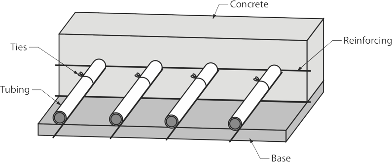
Wherever the tubing makes a turn or return bend, more ties are needed in order to maintain the tube’s shape without kinking. It is important to note here that, if tubing of PeX “B” or “C” is used, any kink in tubing will damage it, and the tube must be replaced. PeX “A” however can be repaired if kinked, simply by heating it with a heat gun (never an open flame!). Even though manufacturers of PeX “A” may have a different opinion when their expansion-type fittings are used, most AHJs (Authorities Having Jurisdiction)will not allow any joints in tubing that is embedded in concrete. That means that any kinks in PeX “B” or “C” will result in the replacement of entire loops unless the damaged portion of the loop is re-routed to a nearby wall where it is brought up out of the slab, repaired and then returned into the slab to continue with regular layout. In order to minimize downward heat loss, and to help drive the heat upward, heated basement slabs should have a minimum of 2 ½” of rigid polystyrene foam between the vapour barrier and the slab bottom. This is especially necessary if there is a heat sink beneath the slab, such as a high water table. Depending on the type of fill under the slab and the presence or absence of a heat sink, many designers and installers will only use under-slab insulation for the outer 2 feet of slab where it contacts the foundation wall. The theory here is that, not long after initial operation, the ground temperature will stabilize and the downward heat loss will be negligible.
Concrete Over Wood Subfloors
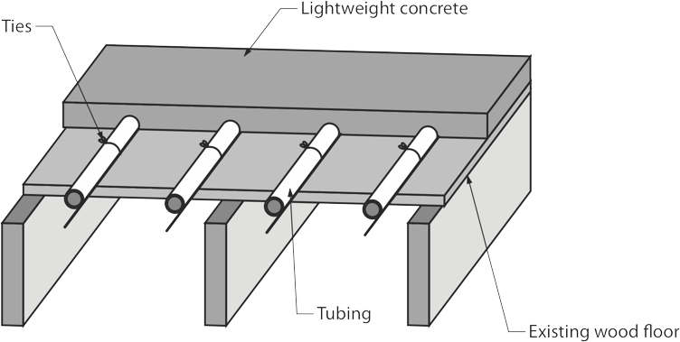
For floors above grade, a lightweight, 1 ½″ thick concrete/gypsum mixture is poured in two “lifts” over ½” tubing stapled to the plywood subfloor (most common) or pressed into channels in pre-formed plastic mats (less common). Just as in the basement slabs, care must be taken to not kink the tube. In that event, a narrow channel can be cut in the wood subfloor immediately below the tube. The damaged portion is routed through the channel into the ceiling below where the damaged portion is repaired and is considered “accessible’ by cutting into the drywalled ceiling if the repair should ever fail. When concrete-over-wooden-subfloor systems are installed, there is an extra bottom plate installed under all the exterior and interior walls that is wider than the regular bottom plate. There are three reasons for this extra plate.
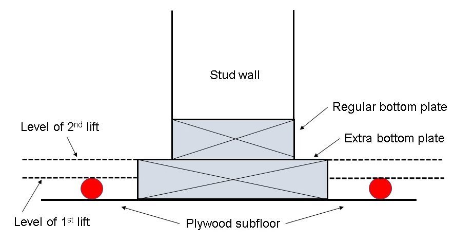
The first is to act as a “screed” for the final height of the second lift of concrete. The first lift is only ¾″ thick which takes it to the top of the tubing. The second lift completes the 1 ½” thick profile and the wider bottom plate acts as a screed for leveling the 2nd lift. The second reason is to be an area where the “smooth-edge” (carpet tack strip) is nailed to, if carpet floor covering is being installed. The third reason is to regain the lost 1 ½″ of ceiling height that is taken up by the concrete.
The other variety of wet system is found outdoors as a snow melt system. PeX tubing is embedded in the concrete of sidewalks and driveways, so as to keep snow and ice from accumulating by circulating an antifreeze or brine solution through the tubing. As such, these systems are usually separated from the building heating system by the use of a heat exchanger.
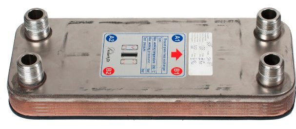
The heat exchanger would be this system’s “boiler”, and would require the use of its own expansion tank, circulator and makeup water. A heightened level of backflow preventer is usually needed for any system that has any chemicals, including salt, that are mixed with water.
Because of the high thermal mass of a wet system, they take time to heat up and cool down. Due to this fact, an indoor wet system is expected to operate at a constant temperature. Night setback thermostats are never a good option for a wet indoor radiant system. Snow melt systems, on the other hand, would be very costly to operate if left to run constantly at a set temperature, so they are normally only brought on when needed. Control systems and sensors can be installed outdoors and embedded in the slab to monitor the slab’s temperature and the presence of snow and ice, thereby limiting the amount of time that the system needs to operate in order to do its job.
“Dry” Systems
If the style of construction can’t accommodate a wet installation, there are a few different ways in which radiant heat may still be utilized.
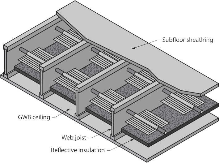
One method is to use the joist space below the floor as a heated channel. A minimum of two PeX tubing runs are either attached to the sides of the joist space about 3 inches below the soffit of the floor (most common), or they are suspended below the floor on special hangers (less common). The tubing heats the joist space and this heat is transferred through the floor to the room above.
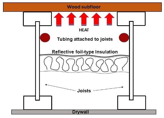
A major down-side to this style of heating is that the air that is trapped in the joist space must act as the heating medium, and air is more of an insulator than a conductor. A better way of applying heat is to run the tubing through grooves in aluminum plates and staple the plates to the underside of the floor. The heat transfer rate is better because of the direct contact between the tubing, the plates and the flooring.
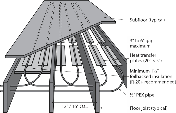
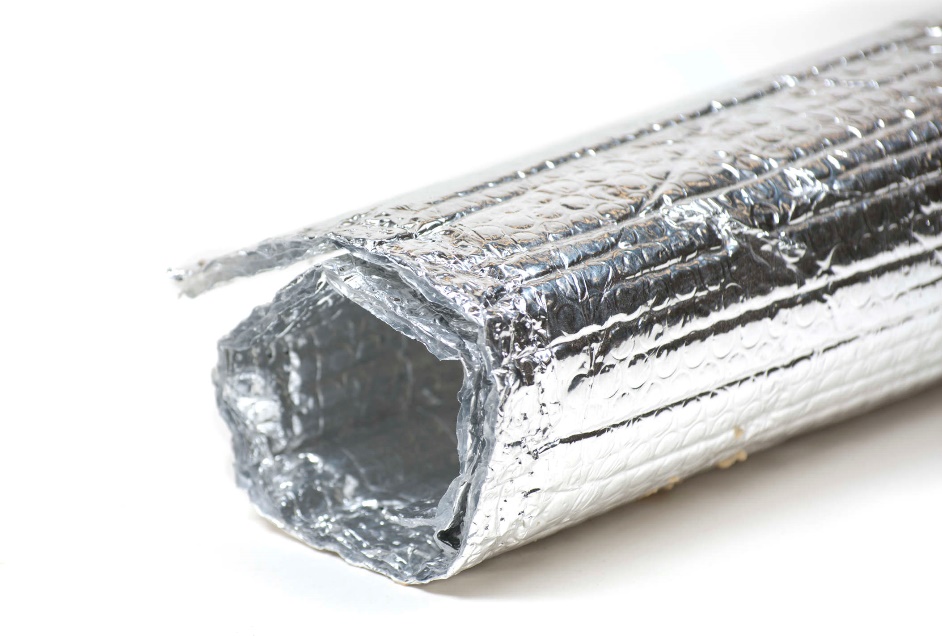
For either of these dry systems, the water temperature has to be much higher than with the wet systems. The bottom of the joist cavity must be insulated when using either type of system. Fiberglass batt insulation can be used and as long as the “R” value of the batts is higher than the “R” value of the subfloor and floor covering above, the heat will be driven upward. A better option would be to use foil-backed insulation in the joist cavity, with the foil facing upward. This helps to reflect any downward radiation from the tubing or plates back toward the soffit.
Aluminum coils that resemble radiators have been developed for dry systems that assist the heat in getting out of the tubing and into the joist space. Although available, they don’t seem to be as popular an option as the aforementioned types and their use is very limited.
Another style of radiant panel should be mentioned here, although usually only found in institutions such as hospitals and schools. Radiant ceiling panels are manufactured to be installed in ceilings directly above windows in hospital rooms and classrooms. Like the other dry-type systems, they have to operate at high temperatures but because they are out of the normal reach of most people, the danger of scalding is avoided. They also have minimal impact on the aesthetics of the room because there is nothing to block the infra-red rays from projecting downward. Furniture placement can’t block the heat flow as it can with forced air or baseboard wall-fin installations.
In some rare cases, such as in a penthouse with a lot of glass, tubing is attached to walls and covered over with plaster. In those installations, anything meant to be hung on the wall would need to be specifically located, to avoid damaging the tubing.
Media Attributions
- Figure 1 Slab-on-grade radiant panel by ITA is licensed under a CC BY-NC-SA licence.
- Figure 2 Wet system on plywood subfloor by ITA is licensed under a CC BY-NC-SA licence.
- Figure 3 Profile at interior wall of wet slab-on-wood-subfloor system by ITA is licensed under a CC BY-NC-SA licence.
- Figure 4 Brazed plate heat exchanger by ITA is licensed under a CC BY-NC-SA licence.
- Figure 5 Dry staple-up system by ITA is licensed under a CC BY-NC-SA licence.
- Figure 6 Typical in-joist dry system using aluminum plates by ITA is licensed under a CC BY-NC-SA licence.
- Figure 7 Reflective foil insulation by ITA is licensed under a CC BY-NC-SA licence.
- Figure 8 Finned plates in a dry system by ITA is licensed under a CC BY-NC-SA licence.
