Learning Task 3
Heat Loss and Heating Requirements
Transmission Loss
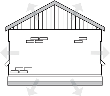
In the heating season, we want to prevent the heat that we’ve put into the building from passing through building materials to the great outdoors. Heat that is lost via conduction through the molecules of the building structure’s materials is known as transmission loss.
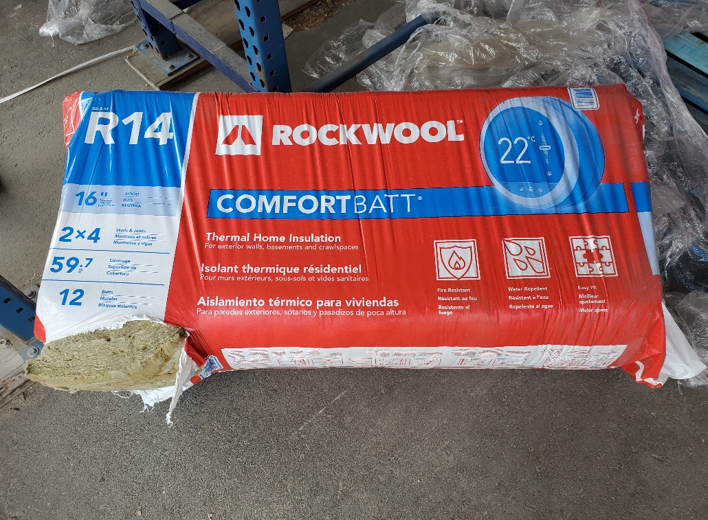
Through many decades now, manufacturers and industry associations have tested and certified the materials commonly used in construction as to their ability to resist the flow of heat through them, and have applied a recognized identifier to them. This identifier is known as an “R” value, with “R” signifying “thermal resistance”. Here’s a common example of a material with its “R” value clearly shown on its packaging.
“R” values are indicative of the number of hours it would take for 1 BTU to pass through 1 ft² of this material when the ΔT between the two sides of the material is 1°F. This is sometimes written as:
R = 12 hrs/btu/ft²/°F
R12 fiberglass insulation is commonly used in 2 × 4 outer wall construction typical of the 1960’s to 1980’s. R14 fiberglass batts can also be found in 2 × 4 construction, but the material is slightly more dense than the R12 and therefore has a better insulating quality to it. Today’s construction, typically using 2 × 6 exterior wall studs, uses R20 to R28 batt insulation or, better yet, spray foam between the studs. In essence, the higher the “R” value, the better the insulator.
An “R” value is an expression of how long, in hours, it would take for 1 BTU to pass through 1 ft² of material when there is a 1°ΔT between the two sides. In the heating industry, however, this expression is exactly backwards to what we need to know. Our industry is based on information expressed in BTUs per hour, not in hours per BTU. To be able to do any of the calculations necessary in building, we must turn an “R” value into what is known as a “K” value. This is done by simply dividing the single material’s “R” value into 1. As an example, if we want to calculate how many BTUs per hour will pass through R14 insulation, we would divide 1 by 14 to get a “K” value of 0.07. This means that 0.07 BTUH will pass through 1 ft² of this material when the ΔT between the two faces is 1°F. If we double the thickness of the material, it will take twice as long for heat to pass through it. And, if we double the ΔT between sides, it will take ½ the time for the heat to pass through.
So, just like our previous calculations regarding BTU calculations and water, there is a formula to use when trying to estimate the transmission losses through a material. The formula is:
Transmission loss = Area (ft²) × “K” value × ΔT (design temperature difference)
Let’s use the R12 material in an example. Suppose we have a 2 × 4 wall that is 15 feet long by 8 feet high, and we’re trying to maintain a temperature on one side of 72°F while the temperature on the other side could be as cold as –10°F. We would have 120 ft² of material, the “K” value would be [latex]\dfrac{1}{12}[/latex] = 0.08 and the ΔT would be 82°F. The calculation would then be:
120 × 0.08 × 82 = 787.2 BTUH
What this means is that, every hour, we could expect 787 BTUs to pass through this 120 ft² of material as a “transmission loss”. We can adopt the widespread rationale within the industry that we don’t use decimals of btus; instead we usually round them to the nearest whole number.
“U” Value
“K” values are not normally involved in calculating heat losses in building construction due to the fact that they are representative of a single material only. Walls are an assembly in the form of drywall, studs, fiberglass batts, wood sheathing, vapour barriers, air films and outside wall coverings such as wood siding or stucco.
When we need to calculate the estimated heat lost through an assembly that is made up of many different materials, we have to come up with an aggregate or summary “R” value. As mentioned previously, every material used in construction will have an “R” value attached to it. In making a list of exterior wall construction from one face to the other, it might look like this, as an example:
Inside air film on ½″ gypsum wall board on vapour barrier on 2 × 6 wood studs with fiberglass batts on [latex]\dfrac{3}{8}[/latex]″ plywood sheathing on lapped, bevelled wood siding on outside air film.
Each of these components has an identified “R” value that can be found in numerous tables in industry publications as well as on the internet. If any values differ between tables, the difference will be very minimal. Here are examples of “R” values that include those in the wall construction listed above.
| Material | R per inch thickness | R for given thickness |
|---|---|---|
| Interior air film | 0.68 | |
| Exterior air film | 0.17 | |
| Gypsum wallboard ½″ | 0.45 | |
| Vapour barrier | Negligible | |
| Fiberglass batt | 4.0 | |
| Polyurethane (spray-in foam) | 5.9 | |
| Concrete block 8″ | 1.11 | |
| Brick, common | 0.20 | |
| Plywood | 1.25 | |
| Polystyrene | 5.00 | |
| Bevelled, lapped siding | 1.05 | |
| Single pane glass | 1.13 |
As you can see, depending on the type of material, the “R” value can be expressed either by the inch of thickness and then adjusted, or by a given thickness. Many materials such as plywood and polystyrene come in many thicknesses so a per-inch value is usually listed once. Other materials such as concrete block and brick are found as certain standard sizes and are listed accordingly.
To assign an aggregate “R” value to the wall listed above, simply identify the “R” value for each material and add them together.
The air that clings to a material’s surface by adhesion has actually been assigned an “R” value. For the wall’s exterior surface, it’s listed as 0.17 and for the interior surface it’s 0.68. Working from inside-to-outside through the wall, the numbers to add together would be:
0.68 (inside air film) + 0.45 (½″ gypsum wallboard) + 0 (vapour barrier) + 22.00 (fiberglass batts) + 0.47 ([latex]\dfrac{3}{8}[/latex]″ plywood sheathing) + 1.05 (bevelled lapped siding) + 0.17 (outside air film) = “R” 24.82
The inside air film, outside air film, ½″ drywall and lapped siding are all unit values, whereas the values for the fiberglass batts and plywood sheathing must be calculated according to thickness. For the fiberglass batts, the “R” value is 4.0 per inch of thickness. Thus, “R” of 4.0 per inch thickness × 5.5″ = “R” of 22.00.
The process is the same for the plywood sheathing; “R” of 1.25 per inch thickness × [latex]\dfrac{3}{8}[/latex]″ = “R” of 0.47
For reasons that are unclear, the plastic vapour barrier that is sandwiched between the drywall and studs is considered to have a “negligible” resistance to the flow of heat and is therefore omitted from heat loss calculations.
Now that we’ve established an aggregate “R” value for a wall assembly, we can come up with a “U” value just as we did for establishing the “K” value for a single material. In our case, we would divide 24.82 into 1 to get “U” of 0.04 (round “R”. “K” and “U” values to two decimals). Remember that a “U” or “K” value is an expression of a material or assembly’s ability to conduct heat through it in BTU/HR, whereas an “R” value is an expression of a material or assembly’s resistance to the flow of heat through it in HOURS/BTU. It should be clear, then, that we are always interested in coming up with the “U” value so it can be used in a multiplication formula to give us a BTUH heat loss. The lower the “U” value, the better the insulator.
It’s important to note that there isn’t much difference between the thermal conductivity of a 2 × 4 wall assembly with wood siding and one with stucco or brick siding. Where the greatest difference lies is in the insulation within the stud space. Exterior walls have been mandated to be at least 2 × 6 construction for many decades now due to the fact that, with an extra 2 inches of insulation in the walls, they are much more energy efficient. The move to 2 × 6 exterior walls versus 2 × 4 was mainly energy-based and not particularly based on strength of the wall.
TECA as well as other associations involved in the heating industry have come up with abbreviated lists of “U” factors. The TECA “U” values are shown in Figure 3 below.
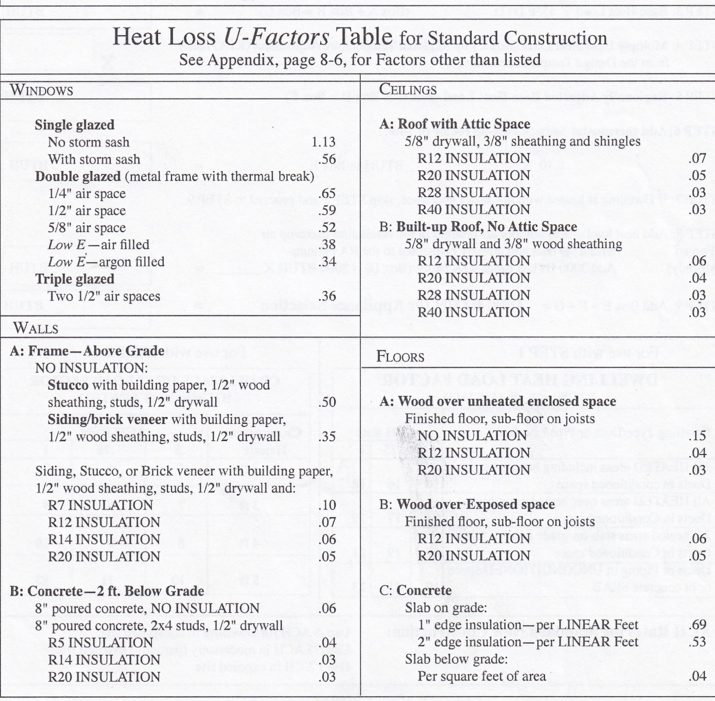
Rather than having to go through the process of identifying all the components of a wall assembly, adding together their “R” values and dividing that into 1 to get a “U” value, one simply has to identify a wall assembly by its general makeup. There is not a lot of variation in wall assemblies used in residential construction, so these “U” values listed are particularly helpful in more quickly obtaining a heat loss while still applying a reasonable degree of accuracy.
Media Attributions
- Figure 1 Transmission losses through the materials of the building envelope via conduction by ITA is licensed under a CC BY-NC-SA licence.
- Figure 2 R14 Batt Insulation by ITA is licensed under a CC BY-NC-SA licence.
- Figure 3 Heat Loss "U-Factors" table is courtesy of TECA BC.
