Learning Task 3
Interpret Electrical Control Circuit Diagrams
Electrical Symbols
By now, you should be familiar with the common symbols used in electrical circuits. Here is a recap of the common symbols used in electrical diagrams and a brief description of their meanings.
| Symbol | Name | Description |
|---|---|---|
| Single Pole Single Throw Switch (SPST) | Opens and closes one circuit | |
 |
Single Pole Double Throw Switch (SPDT) | Opens and closes alternate circuits |
 |
Double Pole Single Throw Switch (DPST) | Opens and closes two separate circuits simultaneously |
 |
Double Pole Double Throw Switch (DPDT) | Opens and closes two alternate circuits simultaneously |
 |
Flow Switch | Closes on flow |
 |
Flow switch | Opens on flow |
 |
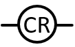
Temperature switch | Opens a circuit on a rise in temperature |
 |
Temperature switch | Closes a circuit on a rise in temperature |
 |
Pressure switch | Closes a circuit on a rise in pressure |
 |
Pressure switch | Opens a circuit on a rise in pressure |
 |
Float Switch | Closes a circuit on a rise in liquid level |
 |
Float switch | Opens a circuit on a rise in liquid level |
 |
Load | Generally, represents a wire winding or coil in a gas valve, light, motor, etc. |
 |
Relay | Typically represents a coil in a relay |
| Wire winding/coil | Similar to “load” above | |
| Transformer | Transformers increase or decrease voltage between primary and secondary circuits | |
 |
Normally open relay contact | Disallows current flow unless relay coil is energized |
 |
Normally closed relay contacts | Allows current flow while coil is not energized |
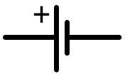 |
Voltage source for direct current | Indicates a battery or other source of DC |
| Resistor | Indicates a constant resistance in a circuit | |
| Variable Resistor | Indicates a resistance that can be changed in a circuit | |
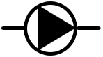 |
Pump | The point of the shaded triangle indicates the direction of flow |
| Fuse | Opens a circuit when too much current flows | |
| Fuse | Same as above | |
 |
Ground (Earth) | A connection to the earth that has no voltage potential |
 |
Wire connection | The dot indicates that there is a connection between wires |
Wiring Diagrams
Let’s look at wiring diagrams that represent a 2-temperature system with high and low temperature loads within it. A low mass non-condensing boiler is feeding an indirectly-fired hot water tank as well as a circuit of baseboard wall-fin emitters. The low temperature system will consist of two independantly-operating manifolds supplying RFPs. The schematic diagram is shown below.
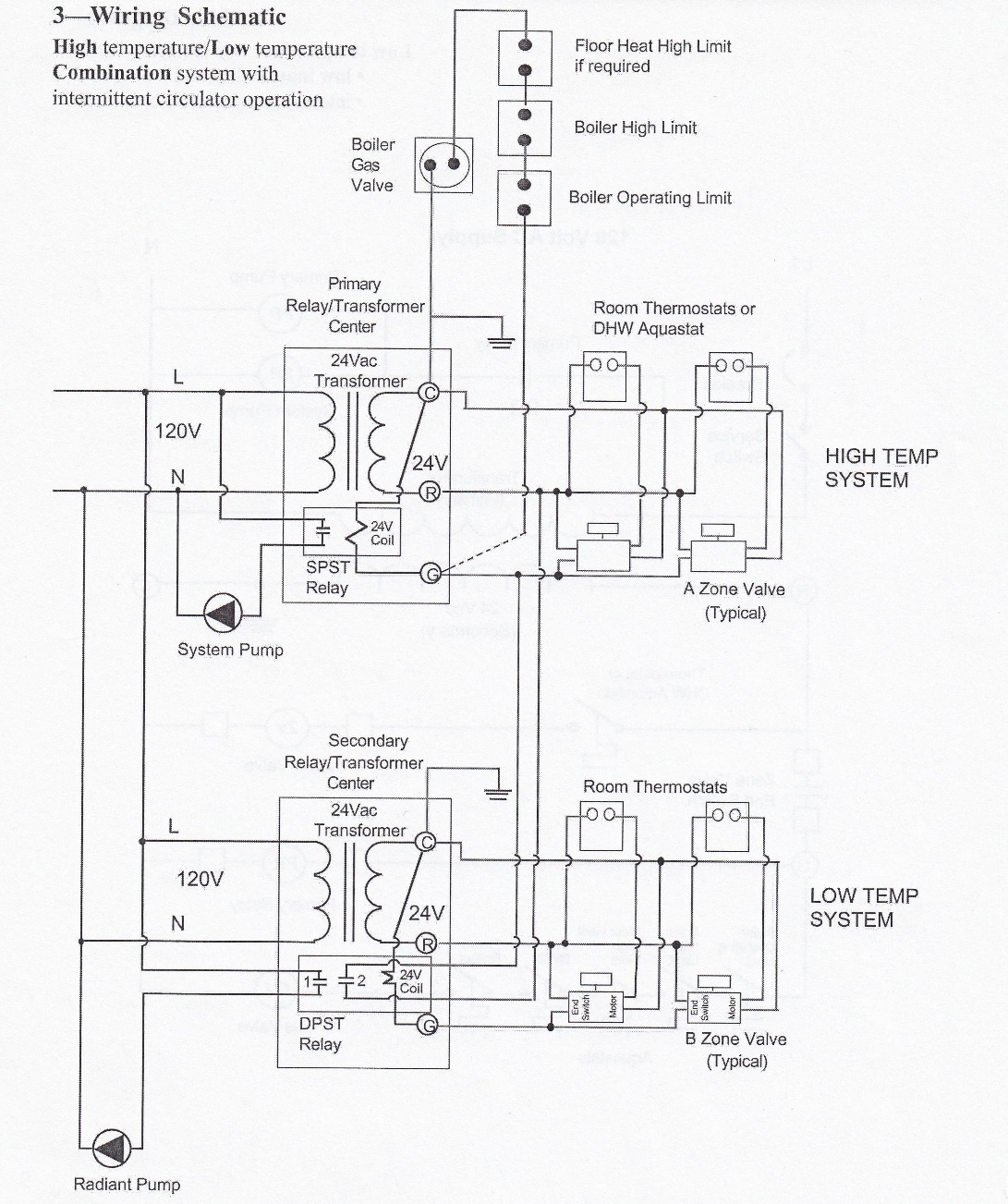
The ladder diagram for this same system is shown below. You can refer to either diagram to follow the commentary on its sequence of operation.
If the DHW aquastat closes on a call for heat, 24VAC from the “R” terminal on the transformer/relay centre is fed to the zone valve motor for the DHW piping system. The motor drives open and the end switch contacts close. This allows 24VAC to power the “G” terminal on the primary relay, and two things will happen simultaneously.
Firstly, the coil on the relay is energized, which closes the N.O. set of contacts of the SPST relay. The 120VAC that were present at the common terminal of the relay will now power the pump, which operates to push water through the boiler and the open DHW zone.
Secondly, the external wiring that is connected at the “G” terminal of the relay allows 24VAC to the burner circuit. This is the circuit that contains all the limit switches for the boiler’s operation. As long as there aren’t any unsfae conditions being sensed, all the switches will be closed and the burner will fire until one of the switches opens. This is normally the aquastat for the boiler itself. It is the control that is commonly set to 180°F. If this temperature is reached, the burner will shut off until the temperature drops to its lower setpoint at which time it will once again make and bring the burner back on, all the while not interfering with the operation of the pump.
When the DHW tank comes up to its setpoint temperature (normally 140°F) the aquastat contacts will open and cut power to the zone valve. The spring on the zone valve motor will return the valve to its closed position, and as soon as the end switch opens, power is also cut to the relay’s “G” terminal, which de-energizes the relay coil to stop the pump and interrupt 24VAC to the burner circuit.
One thing to note on both diagrams is the relationship between all of the end switches and the primary relay. If only a high temperature zone calls for heat, it is only the primary pump that needs to operate. However, if any low temperature zone calls for heat, both pumps must be energized. The key to understanding this operation is through the recognition that the “G” terminal of the primary relay is also connected to a N.O. contact from the secondary relay/transformer center, fed by 24VAC from the primary transformer. This secondary centre has a DPST relay attached to it. In other words, when its 24VAC relay coil is energized, two sets of N.O. contacts will close. One set has 120VAC wired to it and will allow 120VAC to the secondary pump when it closes. The other set has 24VAC wired to it from the “R” terminal of the primary transformer , which allows that power to get back to the “G” terminal on the primary relay so that the other (main) pump will come on. The secondary pump will be the one that is driving water through whatever mixing device is being used, and for it to be able to do its job the primary pump must also be operating. For the high temperature circuits, only the primary pump has to operate.
You should also be able to follow the paths for power through the ladder diagram. One by one, trace the paths through the schematic and ladder diagrams at the same time. Close a thermostat on the high temperature system first, and then do the same for a thermostat on the low temperature system. This will help in understanding the paths that current must follow in order for the system to do what it is supposed to do.
You may also see that there aren’t as many circuits shown on the ladder diagram as there are on the schematic. Sometimes only one circuit is shown if it is the same as other circuits on that system. As well, the components of the relay (coil and contacts) aren’t shown side-by-side like they are on the schematic, so they must be marked to be better understood. The two N.O. contacts that operate the two pumps are shown in parallel to each other on the 120VAC side of the drawing but the actual contacts are contained in two separate pieces of equipment. Also the 120VAC side of the secondary transformer isn’t shown because it is not needed to be; it is shown once only in relation to the primary relay/transformer center. Note too that the secondary relay contact 2, which is the one that will turn on the primary pump when a low temp thermostat calls for heat, is wired to the “R” terminal of the primary transformer, as was described above.
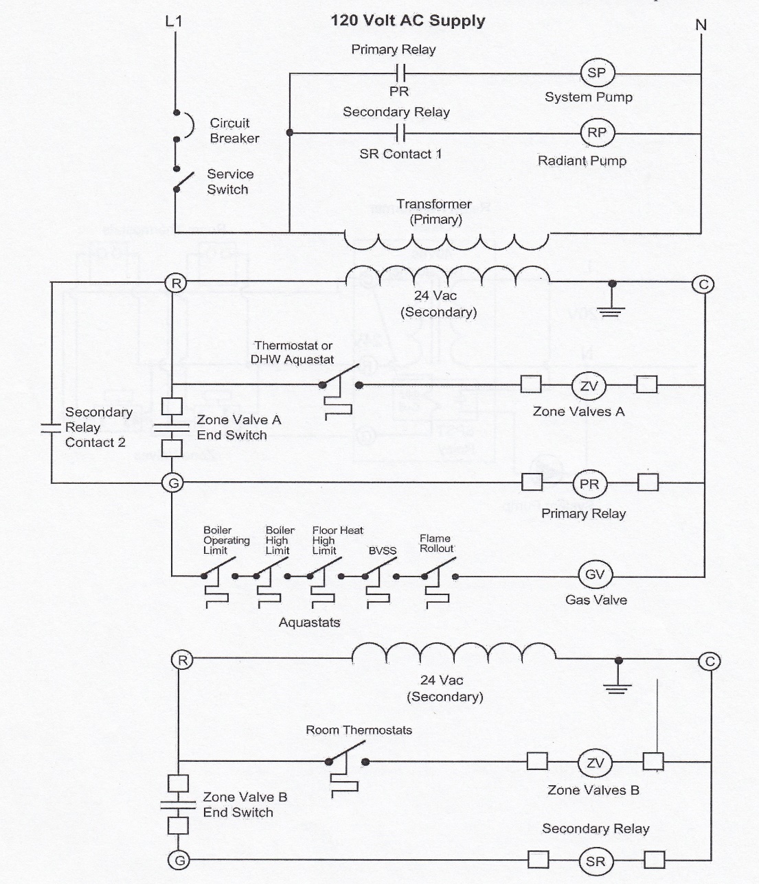
The burner circuit in the diagram above shows 5 limit switches in series. There may be more or there may be less, depending on how many conditions need to be monitored. The boiler operating limit would be the operating aquastat which opens and closes to try to keep the boiler water at its setpoint temperature. The boiler high limit would be N.C. and would only open if for some reason the operating aquastat didn’t open when its setpoint was reached. Any RFP system must have a N.C. high limit on the piping feeding it. This is so that 24VAC to the burner is interrupted if the manifold temperature reaches 20°F above its design temperature, or if the temperature exceeds the manufacturer’s maximum for the PeX tubing fed by the manifold (from TECA BC Hydronic Guidelines). B-vented boilers will have a blocked vent safety switch (BVSS) at the boiler’s draft hood so that the switch will overheat and open if the boiler is spilling its products of combustion instead of allowing them to get safely to the atmosphere through the venting system. The areas around the gas valve and burner inlets will usually have at least one or more SPST switches that will open if exposed to too much heat in that area, caused by conditions such as a plugged heat exchanger, among others. Any safety switches that are meant to sense unsafe conditions are usually located in series with each other in the burner circuit so that, if any switch opens, power to the burner is cut off.
The two diagrams above, with two load centers, are very similar to wiring that would be necessary when there are too many loads for the manufacturer-installed transformer to power. Installers at some point in time will come up against a situation where there are many zones, and zone valves, on their system. Most boiler manufacturers are still producing product whose origin was in the “old days” where there were only two to four zones in the house. In that era, each of the three floors that were typical of a larger house was controlled as a zone, with a fourth possibly being an indirectly-fired domestic hot water tank. One such manufacturer of low-mass, high-temp, low-cost boilers recognized the 4-zone scenario and installed a “zone control board” within their boiler’s controls area. The board had a 40VA transformer built into it as well as connection terminals for four thermostats, and four zone valves with their associated wires for the motors and end switches they contained. This meant that the installer didn’t need to make any 24VAC wiring connections other than from the thermostats and zone valves to the zone boards. The boilers also came with the circulator mounted on the return inlet to the boiler and pre-wired to the controls, making it even easier to wire the system.
Transformer Overload
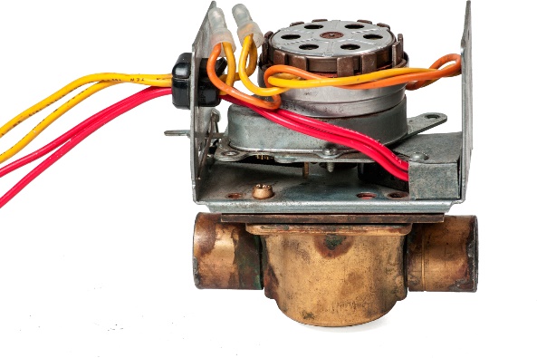
Honeywell©, White-Rodgers© and similar manufacturers of zone valves will publish the amperage draw of their zone valve motors (remember that the end switch inside these units draws no power). For a typical Honeywell© 2 or 4-wire zone valve, the current draw is 0.32 amps.
When looking at either the schematic or the ladder diagram, trace the wires back from the “C” terminal of the transformer. The first item encountered on any of those paths will be a load, as loads are connected to the “C” terminal in order to work, and it is the load that consumes the amperage.
Looking at the previous 2-temperature wiring diagrams, the loads fed by the primary transformer are the high temp zone valve motors, the primary relay coil and the gas valve. Each of these loads have a typical current draw of somewhere in the neighbourhood of 0.3 amps (in the field, the actual draw must be determined). For our diagrams, this means that, if we have two high-temp zone valves, a primary relay coil and a gas valve to power with 24VAC, the current being pushed out by the primary transformer will have to be 1.2 amps (0.3 × 4). The primary transformer is normally already mounted to the boiler, as the burner circuit will be pre-wired. If the transformer is rated for 40VA (40 Watts), it will be capable of a maximum amperage of 1.67 amps, remembering from Ohm’s Law that VA ÷ V (volts) = A (amps), or VA ÷ A = V. We could therefore power one more zone valve (another 0.3A) from this transformer without exceeding its maximum rated output. If any more than 1 extra zone valve are added, the amperage draw will exceed the transformer’s limit, and although nothing immediate would likely happen, if all the zones were open the transformer would be overloaded and would heat up to the point where it would burn out. A burnt transformer is a sign that here are too many loads being powered and that somebody hasn’t done their math correctly.
Below are a schematic and ladder diagram showing the wiring needed when an extra transformer is added to power more zones. Note the similarity between these diagrams and the previous 2-temperature diagrams.
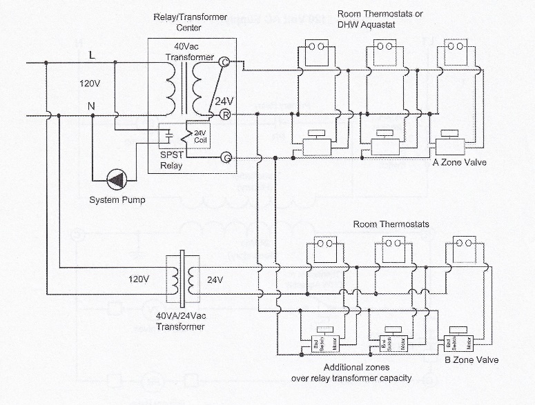
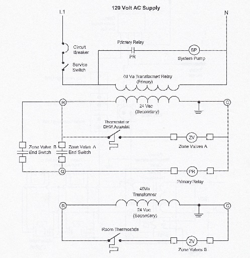
As in the 2-temp diagrams, note that the addition of the extra transformer is only for the extra zone valve motors, as they are the reasons for the extra current draws. They and the thermostats that control them are powered from the added transformer; the end switches of the new zone valves aren’t loads and don’t consume amperage, so they are connected to the same terminal that powers the original end switches. The closure of any end switch will power the relay coil and the burner circuit.
“Zone control boards” are great boons to the process of adding zones to systems. They are available from various manufacturers such as Taco©, tekmar© and Viega© among others. These boards are remotely mounted on an electrical device box near the boiler and are powered with 120VAC to supply the pumps that are controlled by the board. They contain either one or two 40VA transformers depending on the number of zone valves they will operate. Typically, a module for up to 4 zone valves will have a single 40VA transformer mounted within it, and an 8 zone module will contain (2) – 40VA transformers. Most of these types of controllers will be equipped with a “priority” zone. This is usually the zone that feeds an indirect domestic water heater. With priority control, when the DHW heater calls for heat, any other zones will be shut off until the call for heat at the water heater is satisfied. If the priority call lasts longer than 1 hour, the priority is cancelled for a short time so that the rest of the building can regain some heat, and if still needed the DHW priority is once again initiated which again shuts off the building heat. The zone controller shown below is a Viega© 18060 4-zone controller with priority. The wiring diagramfor it shows the connection points on the module. Zone 4 is the priority zone where the zone valve for the indirect domestic water would be connected. If it calls for heat, the other zones are temporarily de-energized.


There are distinct advantages in using any of the zone control modules mentioned above. They set out the number of zone valves that they can accommodate, are furnished with a road map of the wiring connections, and as long as the installer can understand a wiring diagram, success is unavoidable.
Analyzing Circuit Operation
When an electrical circuit won’t operate as it should, diagnostic steps need to be followed in order to pinpoint the problem. The first priority is to understand the sequence of operation. If a technician isn’t familiar with the equipment, the ladder diagram can be used in lieu of a published troubleshooting flow chart.
Measuring Voltage
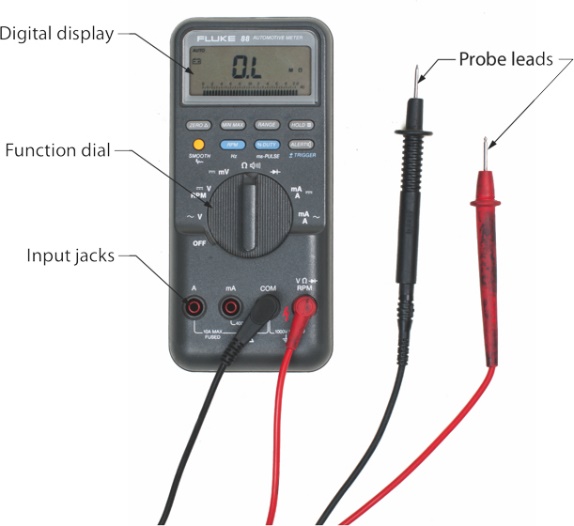
Any diagnostics of electrical circuits will require the use of a multi-meter, in particular the voltmeter function within it. A voltmeter contained within a “VOM” (volt-ohmmeter) will tell you where voltage is or isn’t present and its value. One such use of a meter is shown below. With the meter set to measure AC voltage, a check across the points in the diagram as shown below would read:
1 = 0 volts; 2 = 0 volts; 3 = 24 volts; 4 = 0 volts and 5 = 0 volts.
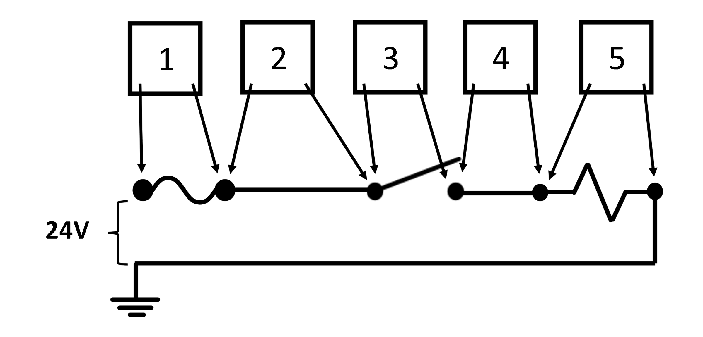
Remember that a voltmeter will always tell you the difference in volts between the two meter leads. If a voltmeter reads “0”, it could be because either:
- there is no voltage present at all at either of the leads, or
- the two leads are being exposed to the same voltage, or
- the meter isn’t working properly
DON’T BE FOOLED BY A “0” READING!!!! Assuming that there is no voltage present could be life-threatening! Firstly, always check a known live circuit to ensure that the meter is functioning properly. Secondly, it may be a better idea to ground one of the leads and use the other to determine exactly where voltage is or isn’t present. Looking at the same circuit but using the meter in a different way, as shown below, these readings should be present if the switch is in the open position.
1 = 24 volts; 2 = 24 volts; 3 = 0 volts; 4 = 0 volts and 5 = 0 volts
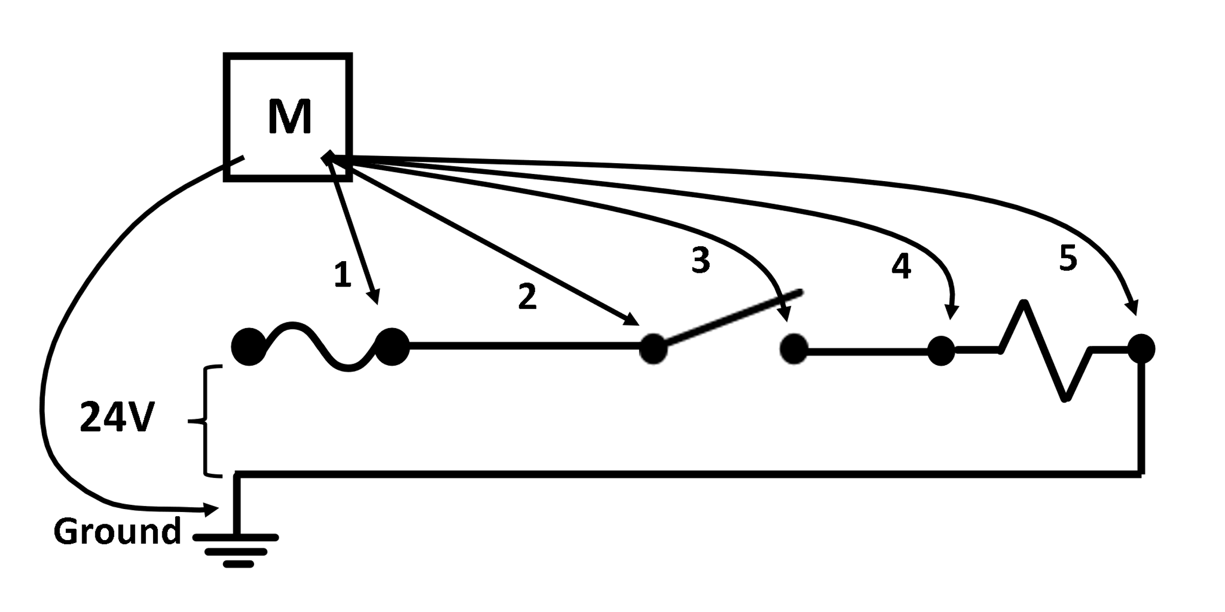
This would tell us that the circuit is live up to the switch. If there is no voltage present beyond the switch, the switch is either in the open position or is closed and faulty.
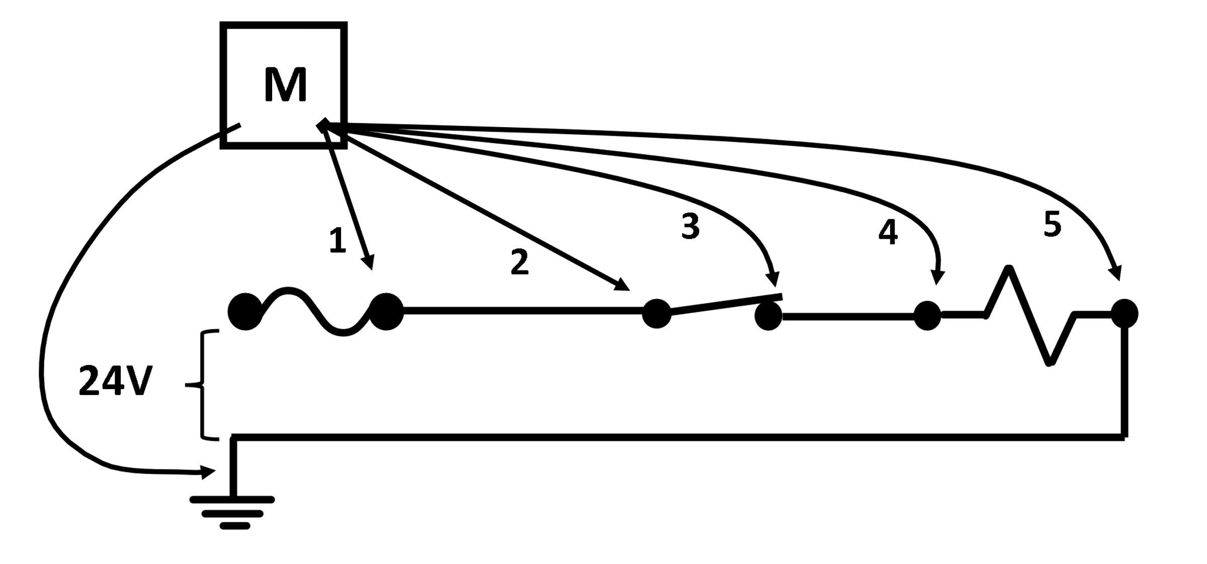
In the diagram above, the expected readings at the meter positions shown, with the switch in the closed position, would be 24 volts at points 1 through 4, and “0” volts at position 5, and the load should be operating. If the load isn’t operating and the readings at positions 1 through 4 are all 24 volts, then either:
- there is a faulty wiring connection between the load and the ground, or
- the load is receiving voltage but is faulty
So, if a circuit isn’t operating, the safest way to test the circuit is by using a multimeter set to measure volts. With the circuit powered, ground one of the leads and use the other lead to check to see where the voltage isn’t present in the circuit. That would be the place where there is an opening, which would either be an open switch, a loose wiring connection or a faulty component.
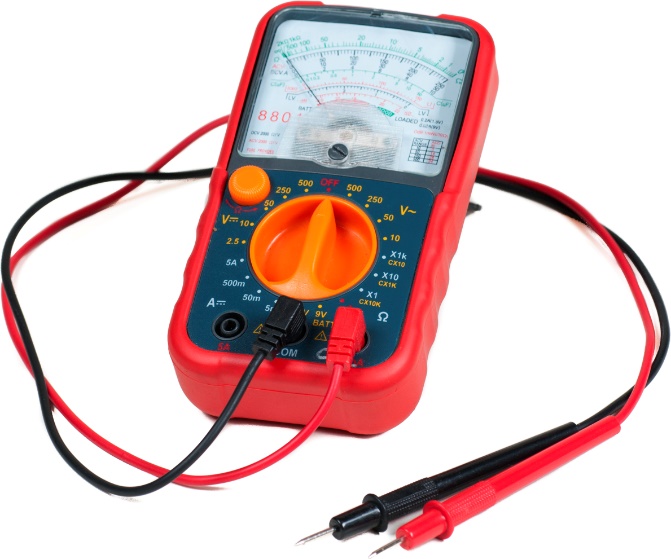
If using a digital multimeter, as shown below, polarizing the leads isn’t necessary when checking DC voltage. If the leads are reversed in polarity, a “minus” sign appears in front of the voltage measured, and no action is necessary as the meter isn’t being harmed.
However, if using an analog meter to measure DC voltage, as shown below, the meter leads must be polarized to avoid damage to the meter. A “tap” test will ensure the polarity is correct. Simply attach one lead to one of the points being measured and tap the other lead on the other measurement point. If the meter’s pointer moves in the right direction, polarity is correct; if it deflects in the wrong direction, polarity is incorrect, the meter could suffer damage and the meter leads must be reversed. Digital meters automatically correct for improper polarity to avoid meter damage.
Measuring Amperage
It is sometimes necessary to check current flow through a circuit. This is harder to accomplish than a voltage check. When voltage is being measured, there is no need to disconnect wires because the voltmeter is used in parallel with the circuit being tested. Ammeters, on the other hand, must be installed in series with the circuit or components being checked. This would require that a wire is removed and the meter leads are connected between the wire and the point that the wire is removed from. As well, the meter leads must be at least as heavy in wire gauge as the wiring in the circuit being checked, and this usually is not the case for multimeters. The easiest way to check for amperage (current flow) in a circuit is to use a clamp-on ammeter as shown below.
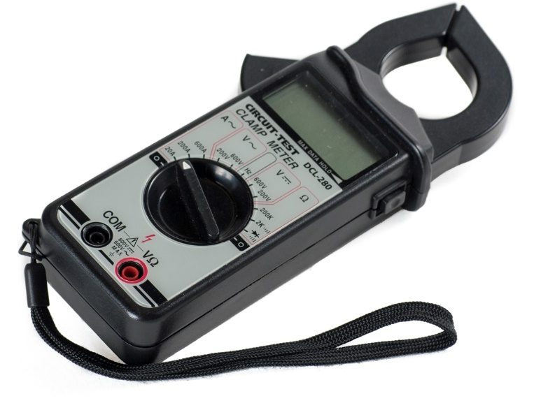
To use the meter, set the range indicator to measure the type of amperage in the circuit (AC or DC), open the jaws by pressing the lever on the side of the meter and capture the single wire being measured within the “circle” of the jaws. Close the circuit so that it is energized and the load is operating. Any current flow through a conductor will create a magnetic field around it, and the meter will measure the strength of the field and translate it into amperage. If the current flow is very small, it may be difficult to measure. If there is enough slack in the wire, wrap it into a coil, counting how many wraps are in the coil. Insert one side of the jaws into the coil, take the measurement and then divide by the number of wraps to get the true current flow.
It is important to make sure that it is only a single wire inside the jaws and not a cable of 2 or more wires. The magnetic fields created in a 2-wire cable will be in reverse polarity to each other and will cancel each other out, resulting in a “0” reading.
Measuring Resistance
A VOM contains a battery, usually 9VDC. If the VOM is of the digital variety, the battery not only powers the solid state board for the display but also provides a power source for the ohmmeter function. An analog meter uses the battery strictly for the ohmmeter within it and both types of meters will have a fuse in them as well. If the Ohms function won’t work, it is likely because the battery is depleted, in which case the digital meter will usually have a “low battery” notice pop up. There is no such notice on an analog meter. Check that the fuse is intact in either case.
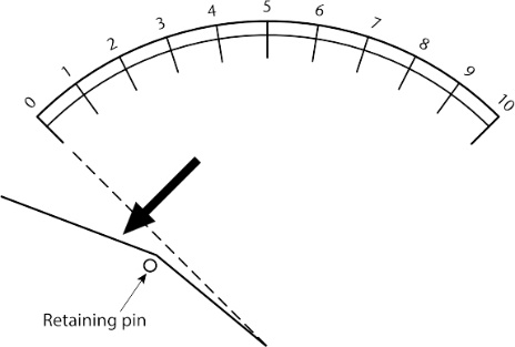
Am Ohmmeter pushes current from the on-board battery out through one lead, through the device or circuit being tested and back and will measure the resistance it encounters. Depending on the selector switch position, the reading will then have to be multiplied by the selected factor (Ohms × 1K; Ohms × 100K, etc). Before using the ohmmeter it must be “zeroed”. Set the selector switch to any of the positions that have the “Omega” sign (Ω) and touch the meter leads together. The reading should be “0” ohms (all the way to the right end on an analog meter). If the needle is off “0” at all, it can be adjusted by using the thumbwheel as seen in the image below. On the analog meter, the Ohms scale is the one at the very top of the scales. It’s a non-linear scale, meaning that a pointer position halfway between the left and right extremeties is not ½ of a full reading such as it is when using either the amperage or voltage functions, as there is no “halfway” measurement between fully connected with no resistance and an infinite amount of resistance such as would result froma missing or broken wire. If the circuit being tested has continuity (isn’t broken) and no resistance, the needle will move all the way to the right and hover directly over the “0” mark.
The thing to always remember when using either the digital or analog meters for Ohms measurement is that the circuit must not be powered. If it is, the best outcome would be that the fuse inside the meter trips; the worst would be damage to the meter. Use the voltmeter to check for power before checking for resistance.
Safety
Whenever a circuit or piece of equipment is opened for inspection, it should be powered off and locked out unless power is needed for readings. If that is the case, use extreme caution, especially around 120VAC, and use the meter to verify that any points that you may come into contact with are live or dead. Have manufacturer’s literature handy, not only for expected readings but for troubleshooting tips. Manufacturers include troubleshooting flow charts in their literature and these are sometimes the best and easiest way to track down problems and determine solutions. Most boiler manufacturers’ flow charts involve meter checks and will lead you through the process. This is a good example of why our gas codes specify that the literature for gas equipment be left with the homeowner. Fortunately, the internet is there for us when onsite manuals aren’t present.
Remember that being shocked by live equipment is a possibility, so make sure that there is a plan in place in the event that it occurs. Have someone nearby if assistance is needed, with access to 911 calls and possibly an Automated External Defibrillator (AED). Exposure to even mild electric shock can knock a heart out of its natural rhythm, so being alone when testing electricity is not a good idea.
Now complete the self-test below.
Self-Test 4
Self-Test 4
- Which one of the following would not be a means of providing low temperature water for a hydronic system?
- The use of a mixing valve
- The use of a diverting valve
- The use of a variable speed injection pump
- Lowering the aquastat setting on a non-condensing boiler
- What is used to “scrub” latent heat from a condensing boiler?
- A primary heat exchanger
- A secondary heat exchanger
- A tertiary heat exchanger
- A direct vent heat exchanger
- What is the principle behind the use of multiple pumps for proper flow rates in a primary/secondary piping system?
- The use of direct return piping layout
- The use of Monoflo © tees
- Hydraulic separation
- AFUE
- Tees in a primary/secondary system should be placed no farther than a maximum of diameters apart.
- 2
- 3
- 4
- 5
- One USGPM will deliver BTUH if the ΔT is 20°F.
- 5,000
- 7,500
- 10,000
- 20,000
- What device, contained within a 4-wire zone valve, ensures that the pump won’t start and the burner won’t fire unless the zone valve is open?
- An end switch
- A thermostat
- An aquastat
- A relay
- What is term is sometimes given to a low-mass boiler?
- Hot start
- Cold start
- Warm start
- Tempered start
- What is a main feature of a ladder diagram that makes it easy to follow?
- The components are shown to scale
- The components are shown as they might be seen
- The lines that represent wires will cross each other
- The lines that represent wires won’t cross each other
- Where are the low voltage terminals located on a relay/transformer centre?
- Inside the transformer
- Inside the junction box
- On the face of the transformer
- On the back of the junction box
- Which terminal on a relay/transformer center is the 24VAC neutral?
- “C”
- “R”
- “Y”
- “G”
- Which terminal on a relay/transformer center powers all the thermostats and end switches?
- “C”
- “R”
- “Y”
- “G”
- Which terminal(s) on a relay/transformer center would be wired to an A/C system?
- “C” and “N”
- “R” and “G”
- “G” and “N”
- “Y” and “W”
- Where in the piping would a 3-way mixing valve be located?
- At the mixing point
- In the boiler return piping
- In the piping to the expansion tank
- At the highest point in the system
- Where in the piping would a 3-way diverting valve be located?
- At the mixing point
- In the boiler return piping
- In the piping to the expansion tank
- At the highest point in the system
- What is the main advantage for using a 3-way diverting valve rather than a 3-way mixing valve?
- The diverting valve is located at the mixing point
- A mixing valve has less head loss than a diverting valve
- A diverting valve has less head loss than a mixing valve
- The mixing valve needs a motorized controller in order to work properly
- What is one main disadvantage of using a 3-way diverting valve rather than a 3-way mixing valve?
- It needs a remote sensor
- It needs a motor controller
- It needs an outdoor reset control
- It has a higher head loss through it
- How many inlets and outlets does a 3-way diverting valve have?
- 2 inlets and 1 outlet
- 1 inlet and 2 outlets
- 3 outlets
- 3 inlets
- Which one of the choices below is considered to be the best option for tempering water to a low temp system due to its very low head loss?
- A 2-way injection valve
- A 3-way mixing valve
- A 3-way diverting valve
- A 4-way mixing valve
- What is the term given to a controller than automatically adjusts system water temperature when the temperature outside rises or falls?
- Outdoor sensing
- Indoor sensing
- Outdoor reset
- Indoor reset
- What is the equation used to calculate the curve for an outdoor reset control?
- (room temp − outdoor temp) × (design supply temp + outdoor tem)
- (outdoor temp − room temp) ÷ (outdoor temp − design supply temp)
- (design supply temp − room temp) ÷ (room temp − outdoor design temp)
- (design supply temp × room temp) ÷ (room temp × outdoor design temp)
- What is the setting known as where, on an outdoor reset control, the indoor and outdoor temperatures are equal, causing the system to shut itself off?
- Warm weather shutdown point (WWSD)
- System design temperature shutoff (SDTS)
- Outdoor shutdown point (OSP)
- Indoor heat shutdown (HIS)
- What is the meaning of the symbol shown to the right?
- A flow switch
- A pressure switch
- A heating thermostat
- A cooling thermostat
- What is the meaning of the symbol shown to the right?
- A DPDT switch
- A DPST switch
- A SPST switch
- A SPDT switch
- What is the meaning of the symbol shown to the right?
- A normal closed relay contact
- A pressure switch
- A transformer
- A coil
- What is the next event that occurs after a zone thermostat closes?
- The pump starts
- The burner fires
- The zone valve opens
- The end switch opens
- What happens when 24VAC is sent to the “G” terminal on a primary relay/transformer centre that is controlling a non-condensing boiler using a single pump?
- The burner fires and the pump shuts off
- The pump turns on and the end switch opens
- The pump turns on and the burner fires
- The boiler aquastat and thermostat open
- What is the normal temperature setting for an indirectly-fired domestic water heater?
- 140°F
- 160°F
- 180°F
- 200°F
- How many contacts are needed on a secondary relay/transformer centre to make the primary and secondary pumps start in a 2-temperature system?
- One N.C. contact
- Two N.C. contacts
- One N.O. contact
- Two N.O. contacts
- Looking at a ladder diagram, if you follow a path from the “C” terminal of a transformer backwards through the diagram, you will find the .
- Loads
- Sources
- Switches
- Main disconnect
- In what arrangement and into which circuit are all the limit switches wired for a hydronic system that uses a gas boiler?
- In series, in the burner circuit
- In parallel, in the burner circuit
- In series, in the circulator circuit
- In parallel, in the circulator circuit
- According to the TECA BC Hydronic Guidelines, an RFP must have a N.C. high limit on the piping feeding it that must shut off the burner if the temperature there reaches °F above its design temperature.
- 5
- 10
- 15
- 20
- If needed, where would a “BVSS” be located on a boiler?
- Near the burners
- Near the draft hood
- Near the boiler circulator
- Near the manifold furthest from the boiler
- If an old three storey house had one thermostat and zone valve per floor, yet there were four zone valves on the boiler supply piping, what would normally have been supplied with water through the fourth zone valve?
- A snow melt system
- A swimming pool
- A hot water tank
- A hot tub
- If a transformer was rated at 24VAC and 60VA (Watts), how many amps of current would it be capable of safely supplying?
- 0.40
- 1.67
- 2.50
- 960
- If a secondary transformer is necessary because of too much load, what will it provide power for?
- All the extra equipment including thermostats, zone valve motors and end switches
- Only the extra thermostats and zone valve motors
- Only the extra thermostats and end switches
- Only the gas burner circuit
- What component of a hydronic heating system is wired to the “priority” terminals of a zone control board?
- The pump relay
- The burner circuit
- The DHW zone valve
- The warm weather shutdown control
- When the priority zone calls for heat, which other zones will still operate?
- Only the ones with the highest heat load
- Only one zone on the bottom floor
- Three zones maximum
- None
- A voltmeter will be connected with the circuit or component being tested.
- In series
- In parallel
- Permanently
- Via a bare wire
- An ammeter that isn’t a clamp-on style will be connected with the circuit or component being tested.
- In series
- In parallel
- Permanently
- Via a bare wire
- When checking amperage on a 4-wire cable, using a clamp-on style ammeter, how many wires can be encircled by the meter’s jaws?
- 1
- 2
- 3
- 4
- What is the single most important point listed below when using an ohmmeter?
- Make sure the circuit is low voltage
- Make sure the circuit isn’t powered
- Make sure the leads are soldered to the component being tested
- Make sure to have one hand free to be able to make adjustments
- What would be the next step involved after touching the leads together when “zeroing” an ohmmeter?
- Remove the fuse
- Set the selector switch for DC Ohms
- Turn power on the circuit being checked
- Turn the adjusting screw so that the pointer is directly over “0”
Check your answers using the Self-Test Answer Keys in Appendix 1.
Media Attributions
- All symbols by ITA are licensed under a CC BY-NC-SA licence.
- Figure 1 Schematic diagram of 2-pump, 2-temp system is courtesy of TECA BC.
- Figure 2 Ladder diagram of 2-pump, 2-temp system is courtesy of TECA BC.
- Figure 3 Honeywell © 4-wire zone valve by ITA is licensed under a CC BY-NC-SA licence.
- Figure 4 Schematic diagram for adding a transformer and zone valves is courtesy of TECA BC.
- Figure 5 Ladder diagram for adding a transformer and zone valves is courtesy of TECA BC.
- Figure 6 Viega © 18060 4-zone controller with priority © Viega. Used with permission.
- Figure 7 Wiring diagram for Viega © 18060 © Viega. Used with permission.
- Figure 8 Open circuit readings using a voltmeter, method #1 by ITA is licensed under a CC BY-NC-SA licence.
- Figure 9 Open circuit readings using a voltmeter, method #2 by ITA is licensed under a CC BY-NC-SA licence.
- Figure 10 Closed circuit readings using a voltmeter, method #1 by ITA is licensed under a CC BY-NC-SA licence.
- Figure 11 Digital multimeter by ITA is licensed under a CC BY-NC-SA licence.
- Figure 12 Analog multimeter by ITA is licensed under a CC BY-NC-SA licence.
- Figure 13 Analog meter measuring DC voltage with wrong polarity by ITA is licensed under a CC BY-NC-SA licence.
- Figure 14 Clamp-on ammeter by ITA is licensed under a CC BY-NC-SA licence.
- Figure 15 “Zeroing” an analog Ohmmeter by ITA is licensed under a CC BY-NC-SA licence.
