Learning Task 1
Describe Switches
Although the control systems of today are far more complex and involved than they were a few decades ago, switches and relays are still the heart of the operational systems. They come in many types, shapes, sizes, configurations and electrical designations. It is imperative that the tradesperson who is tasked with installing, maintaining and diagnosing hydronic systems has a basic understanding of how switches and relays work.
What is a Switch?
A switch is a device that makes or breaks (closes or opens) a path in an electrical circuit to allow loads, which are electrical components that perform work, to operate safely and in the manner that is intended.
Manual Switches
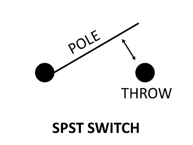
The best and simplest example of a manual switch is a light switch for a room. When the switch is manually moved or “thrown”, the position of the moving part, called the “pole”, changes. If it was in the “off’ position to start with (the pole not touching the contact point called the “throw”), the contacts will close when the switch is thrown and the light will come on. Switches are referred to by the number of poles and throws they have. A bathroom light switch would normally be a single-pole, single-throw switch, as seen in the graphic below.
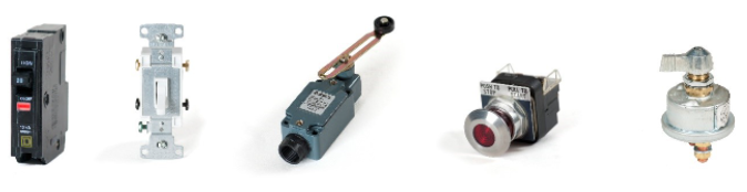
Five varieties of manual switches are shown below.
- Single pole, single throw switch (SPST)
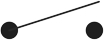
- Single pole, double throw (SPDT)
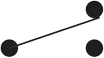
- Double pole, single throw (DPDT)
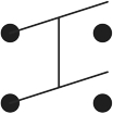
- Double pole, double throw switch (DPDT)
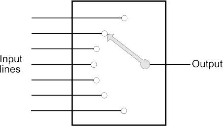
- 7 throw (1P7T or rotary switch)
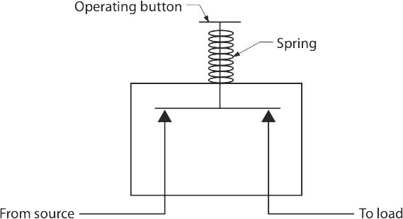
Another variety of manually-operated switch is known as a momentary switch. These must be pushed or turned and held in order for the contacts inside them to close. They are spring-loaded and will snap back to their open position when the button is released.
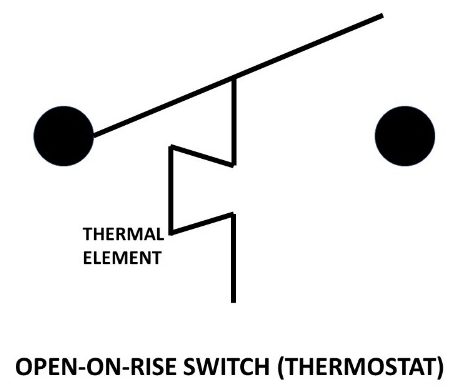
Automatic switches are used to sense, measure and react to conditions such as, but not limited to, temperature, pressure, flow, liquid level and position. They are classified by what they measure and by the condition that causes them to react. For instance, a thermostat used for a heating system will open when the temperature rises to its desired level. This would be classified as “open on rise”. We want the thermostat to open its contacts, in other words shut the heating system off, when the heat it’s measuring reaches its setpoint temperature. When heated enough, the thermal element attached to the pole will rotate or lengthen, depending upon its design, and in doing so will move the pole off of the throw.
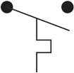
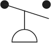
A cooling thermostat, shown below, would be classified as a “close on rise” switch, in that, as the temperature rises, the thermal element that the heat is exposed to will expand and close its contacts to bring on the cooling system. When the temperature surrounding the thermostat drops to the setpoint, the pole is pulled away from the throw and the system is de-energized.
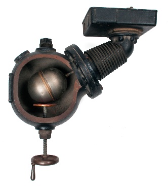
An aquastat is a switch that does for water what a thermostat does for air. Aquastats typically consist of a liquid-filled bulb that is connected to a bellows within the housing of the switch, via a capillary that can be many feet in length. When the liquid expands due to heat being applied to the bulb, the pressure caused by the expansion of the liquid is transferred to the bellows and causes a mechanism to move. This mechanical interaction could cause a valve to snap open or closed, or to open or close slowly (modulate) depending on the style of the aquastat.
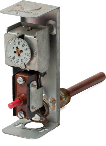
The aquastat shown above has a “thermowell” on the rear, attached to it by a clip. It is the well that actually is inserted into an opening in the piping system. The bulb fits fairly snugly inside the thermowell. A small amount of thermal-conductive grease is applied to the end of the bulb to ensure a more accurate heat transfer via conduction. The use of thermowells allows the aquastat to be replaced without losing any system water.
Many switches have a bit of variance between their open and closed positions. This is known as “differential”, and can either be fixed or adjustable. Many aquastats for hydronic systems have a fixed differential of 15°F (8.33°C). Pressure switches used on well pump systems have differentials pre-set at 20 psi and are adjustable to values a little above or below 20 psi.
In technical terms, the suffix “stat” is meant to signify a switch. The prefix “aqua” indicates water, “thermo” indicates air, a flow switch is known as a “flowstat”, a pressure switch as a “pressurestat” and so on.
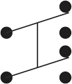
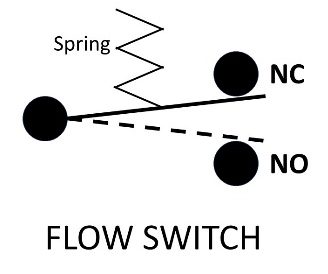
A flow switch has a paddle that is inserted into the branch of a tee in the pipe that it is monitoring. When there is flow, the paddle is moved and the pole of the switch is both pushed onto a throw as well as pulled away from another throw. This is a single pole, double throw type of switch. It can be used to either energize or de-energize a circuit depending on the control strategy required. For instance, a low-mass boiler always needs to have flow through it when the burner is firing. A pump is meant to move water through the boiler, and to prove that the water is actually moving, the flow switch is installed in the piping. The boiler’s burner circuit is wired through the common and “N.O.” (normally open) contacts of the switch. When the paddle is moved by the flow, it closes the normally open contacts and allows power to complete the burner circuit. If the flow stops, the contacts attached to the spring-loaded paddle open, shutting off electricity to the burner circuit. In this case there would be no wire attached to the “N.C.” terminal. This is a single pole, double throw switch as seen below.
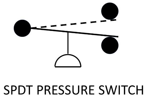
A pressure switch is used on mid-and-high efficiency gas equipment to prove that a venter fan is running and providing the correct amount of air movement before allowing the burner to fire. It can be either a SPDT type, just like the flow switch, or it can simply have one set of “N.O.” contacts. In either case, the contacts close when the correct pressure is sensed. It has its own symbol that is meant to look like a cup that would move if air pushed its way into it, as seen below.
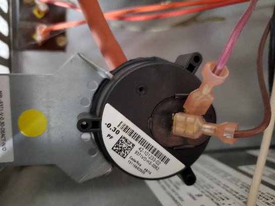
The symbol above would represent the device pictured to its right. This is a pressure switch for a forced air furnace. The orange tube behind the switch is connected to the back of the switch housing and to the outlet side of the venter fan. When pressure is created by the fan, it is relayed to a diaphragm inside the housing. The diaphragm moves an armature, closing the contacts to signify that the fan is not only working but is putting out at least the amount of pressure, in inches water column, that is shown on the switch’s tag (0.3 inches w.c.). When replacing a pressure switch, always use one that has the same pressure setting.
As with the other varieties of switches, they can either be single throw or double throw, and open on rise or close on rise.
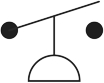
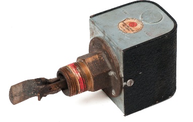
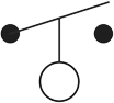
Float switches can be used to monitor the level of liquids in a vessel and will either open or close to control a pump supplying water to a cooling tower sump, or to shut off the burner in a steam or hot water boiler whose water level has dropped to an unacceptable point. This device is known as a low water cutoff. It and the symbol for a float switch are shown below.
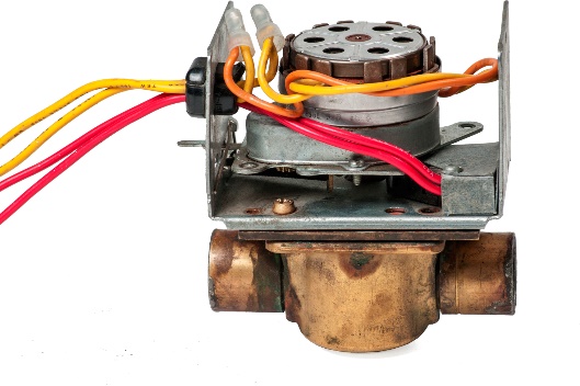
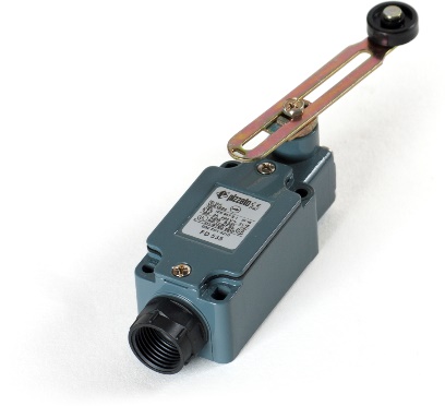
End switches can be used if the position of a piece of mechanical equipment has to be proven before the next step in a sequence of operation can take place. In hydronics, a zone valve has to be proven to be open before the pump tries to move water through it. This prevents the pump from “dead-heading” which must be avoided. A 4-wire zone valve has an end switch wired across two of the wires which typically have red insulation. When 24 volts is applied across the two yellow-coloured wires, the motor of the control head is powered. The rubber ball on the end of the arm connected to the motor swings away from the port that it was covering, allowing the valve to open. When the arm reaches the end of its travel path, it contacts a micro-switch. The switch contacts close to allow 24 volts through the red wires to energize the coil of a relay, which connects to the pump, allowing the pump to start.
Another example of the use of an end switch is in the operation of the dampers on the inlet to a direct-fired makeup air unit (DFMA). These fan-driven units are used to supply tempered air to commercial kitchens while large volumes of air are simultaneously pulled from the space through a separate exhaust system. Before the fans can start, the dampers on the DFMA must be proven to be open. Just like in the motorized zone valve, an end switch is contacted by the damper arm at the end of its run, and power can then be allowed to energize the fans.
A dimmer switch functions as an on/off switch with the addition of a variable resistor built into it. By turning the dial and increasing resistance, less current flows to the bulb which results in less light output. Although dimmer switches are common in building lighting, they don’t see much use in heating systems.
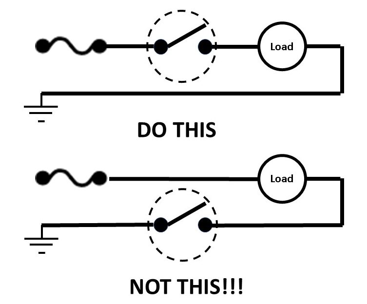
Switches work by opening or closing electrical circuits, and as such, they will do their job no matter where they are located within the circuit. For safety’s sake, they should always be located in the “hot” leg of a circuit. This means that they should be positioned between the source (power supply) and the load (the device that turns electrical energy into work). If switches are installed between the load and its ground connection, the load will still be able to be turned on and off, but the load will still be energized even when the switch is in the open (“off”) position. This is very dangerous, in that electrocution hazards exist if someone were to touch any wiring contacts on the upstream side of the switch. By installing switches in the hot leg of the circuit, no power exists downstream of the switch, so loads can be safely worked on as long as the switch is locked out.
When installing a switch, make sure that its voltage and amperage ratings are at least as high as those it will be exposed to.
Media Attributions
- Figure 1 Switches by ITA is licensed under a CC BY-NC-SA licence.
- All switch icons by ITA are licensed under a CC BY-NC-SA licence.
- Figure 2 Momentary switch by ITA is licensed under a CC BY-NC-SA licence.
- Figure 3 Heating thermostat by ITA is licensed under a CC BY-NC-SA licence.
- Figure 4 Close on rise switch (cooling thermostat) by ITA is licensed under a CC BY-NC-SA licence.
- Figure 5 Close on rise switch (cooling thermostat) by ITA is licensed under a CC BY-NC-SA licence.
- Figure 6 Flow switch by ITA is licensed under a CC BY-NC-SA licence.
- Figure 7 SPDT Switch by ITA is licensed under a CC BY-NC-SA licence.
- Figure 8 SPDT Pressure Switch by ITA is licensed under a CC BY-NC-SA licence.
- Figure 9 SPST pressure switch (NO) by ITA is licensed under a CC BY-NC-SA licence.
- Figure 10 SPST open on rise by ITA is licensed under a CC BY-NC-SA licence.
- Figure 11 SPST close on rise by ITA is licensed under a CC BY-NC-SA licence.
- Figure 12 Low water cutoff by ITA is licensed under a CC BY-NC-SA licence.
- Figure 13 Float switch by ITA is licensed under a CC BY-NC-SA licence.
- Figure 14 Zone valve with end switch by ITA is licensed under a CC BY-NC-SA licence.
- Figure 15 End switch for damper arm by ITA is licensed under a CC BY-NC-SA licence.
- Figure 16 Correct position for a switch in a circuit by ITA is licensed under a CC BY-NC-SA licence.
