Learning Task 1
Describe the Principles of Electrical Controls
The advent of the internet has quite possibly been the biggest boon to hydronics professionals, in that there is a mountain of information available at our fingertips to help guide us through any problems or questions we encounter. Online tutorials, virtual assistants and countless drawings and schematics offer help that once could only be obtained through phone calls to suppliers and by reading through volumes of technical manuals. Installation guides and FAQs take much of the mystery out of our control systems, so that we can make informed choices centred on the function and reliability of a product, rather than sticking with the status quo because of fear of the unknown. This learning module will attempt to help de-mystify some of the aspects of today’s “whole-house” hydronic controls and set learners on the path of understanding the systems they are installing.
Although solid state controls have been around for a number of decades, it has only been within the last thirty or so years that they have been incorporated into residential design. Large commercial buildings usually have on-site professionals whose only job is to oversee the operation of the building’s mechanical systems, which are constantly monitored and displayed through software programs. That job description/person doesn’t exist in a residential home, so control systems for dwellings have to be proven, reliable and very much self-diagnostic as much as possible if a homeowner is to have confidence that they won’t have to routinely call in an expensive tradesperson to troubleshoot their system.
The “Old”
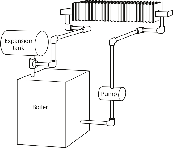
Before PeX and radiant floor panels took over the residential hydronic heating world, systems were very simple. There were only a few choices of types of “conventional” non-condensing boilers (cast iron, copper fin tube and steel) and some basic piping strategies for high temperature systems (series loop, Monoflo© tee and the two 2-pipe systems) that fed baseboard wall-fin emitters. One pump pushed water everywhere and hydronics were simple.
Hydronic radiant floors changed all that.
Non-condensing boilers need high return water temperatures which are too hot for radiant floors. Radiant floors have low-temperature water circulating through them, so the need for multiple temperature piping systems was born. Installers at first attempted to simply turn down the operating setpoint temperature on the boilers, but they soon found out the effects of low temperature return water constantly entering the boiler. This low temperature return water was often below the atmospheric dew point temperature. Consequently, boilers rusted out on the outside and their heat exchangers plugged from the constant sooting caused by condensation dripping onto the burners below them. It was clear that things had to be done differently.
The “New”
If a boiler must run hot, and floors need only to be warm, then there has to be means to have two water temperatures exist within the same system. The use of mixing valves, diverting valves and variable speed injection pumps allows that to be achieved. To enable this to happen, today’s hot water heating systems are now considered “high tech”. More efficiency and comfort can be realized by the use of controls that measure and automatically adjust outdoor, indoor and system water temperatures. A spinoff to the use of high-tech controls is that hydronic cooling is now a viable option where in the past, without sophisticated controls, it wasn’t.
The Heat Plant
The use of stainless steel and other corrosion-resistant alloys in boiler design has progressed. A secondary heat exchanger “scrubs” the latent heat from the flue gases, which increases their “AFUE” (Annual Fuel Utilization Efficiency) and also allows them to operate at lower temperatures. Thus, the condensation they produce won’t cause corrosion problems.
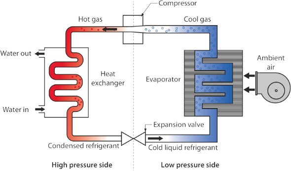
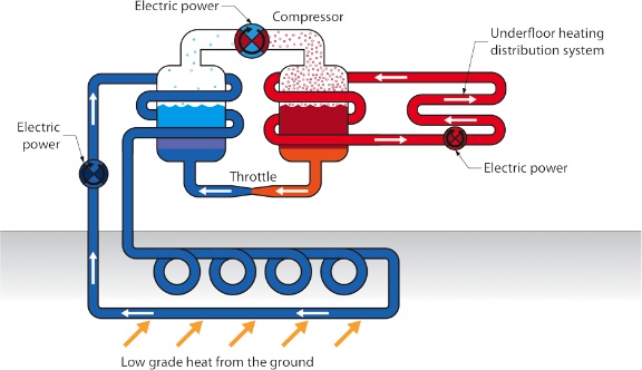
Further to that, air-to-water and water-to-water heat pumps are replacing hydrocarbon-fuelled boilers more and more, so dependency on fossil fuels is greatly reduced, thereby decreasing our carbon footprint.
The Piping
Primary/secondary piping strategies have largely replaced the standard series loop, Monoflo© tee and 2-pipe direct and reverse return piping that hydronics have grown up with.
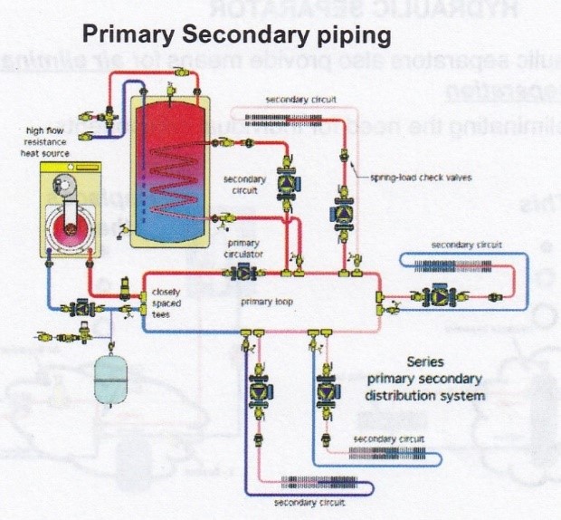
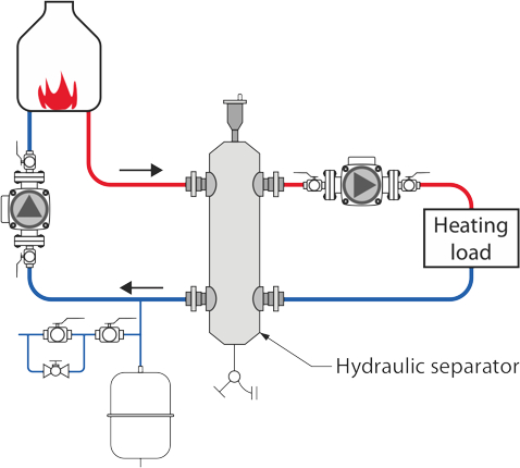
Primary/secondary piping systems rely on the principle of hydraulic separation for proper flow rates. Closely-spaced tees and hydraulic separators are used so that pumps that are connected to the same water system won’t have an effect on each other. Placing tees no farther than 4 pipe diameters from each other ensures that there is minimal pressure drop between the tees. Large containers called “hydraulic separators” perform the same function, often with less room taken up and less connections overall.
Media Attributions
- Figure 1 Non-condensing boiler and wall fin by ITA is licensed under a CC BY-NC-SA licence.
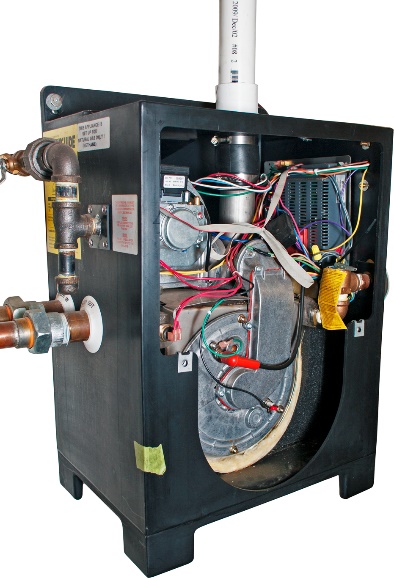
- Figure 2 Small residential condensing boiler by ITA is licensed under a CC BY-NC-SA licence.
- Figure 3 Air-to-water pumps by ITA is licensed under a CC BY-NC-SA licence.
- Figure 4 Water-to-water heat pump by ITA is licensed under a CC BY-NC-SA licence.
- Figure 5 Primary/secondary piping © Viega. Used with permission.
- Figure 6 Hydraulic separatorby ITA is licensed under a CC BY-NC-SA licence.
