Learning Task 2
Describe Control Systems for Hydronic Systems
The Controls
The term “controls” has a very broad scope. Within it are piping strategies and devices that are ultimately governed by “controllers”, and there are many variations and combinations of the above. Viega© is recognized in the industry as one company that produces equipment and literature for different control strategies. They are probably best known worldwide for their innovations in press-type piping fitting technology, but they are also a dominant force in hydronics control. The diagrams below are just a few of the many offered by Viega © that show possible options for system control.

We will be using some of their drawings in this learning module but to be clear, there are far too many variations of piping and control strategies to be able to cover them all. We will pick out some that would most likely apply to today’s residential systems and we’ll endeavour to explain their design characteristics and operation.
With that in mind, let’s first look at an “old-school” system using 2-pipe direct-return layout.
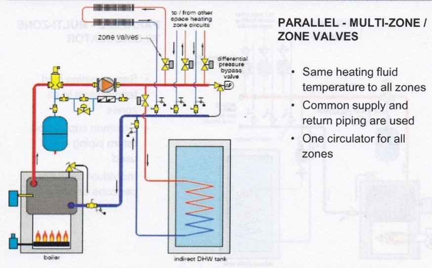
This system used one pump to push water everywhere. The pump would be sized to produce enough head pressure to overcome the losses through the boiler, out through the circuit that had the most frictional resistance and back to the boiler, while being able to push water through all of the circuits if they were all calling for heat simultaneously. In other words, using the industry standard ΔT of 20°F, it would supply a flow of 1 GPM for every 10,000 BTUH of heat needed for the building.
Based upon a 20°FΔT, if the non-condensing boiler’s operating aquastat was set at 180°F, then the system’s average operating temperature would be 170°F. This would be the temperature used to size the baseboard wall-fin and the coil in the domestic hot water tank. The boiler burner circuit would get its 24VAC power supplied to it whenever an end switch on a zone valve closed. This was so that, theoretically, the burner couldn’t fire unless a zone was open and water was flowing. If water flow had to truly be proven and not just assumed, the 24VAC would also have to pass through a flow switch to get to the burner.
The zone valves would be controlled by thermostats and the domestic hot water would be sensed by an aquastat.
If the boiler was of the low-mass variety, the pump and boiler burner circuit should only be energized if a zone valve proved open. If the boiler was high-mass, it could be operated without flow through it and so the burner circuit could always be energized to keep the boiler hot at all times if desired.
Because all aspects of these systems operated at high temperature, they required no mixing valves. The electrical schematic and ladder diagrams for them are similar to these below for a low-mass boiler, which is often referred to as “cold start” because it can’t fire to keep itself hot unless there is a call for heat from the system.
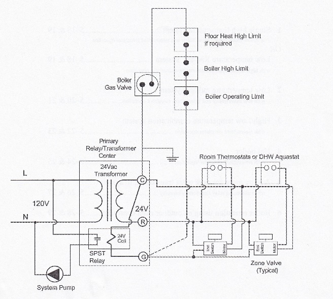
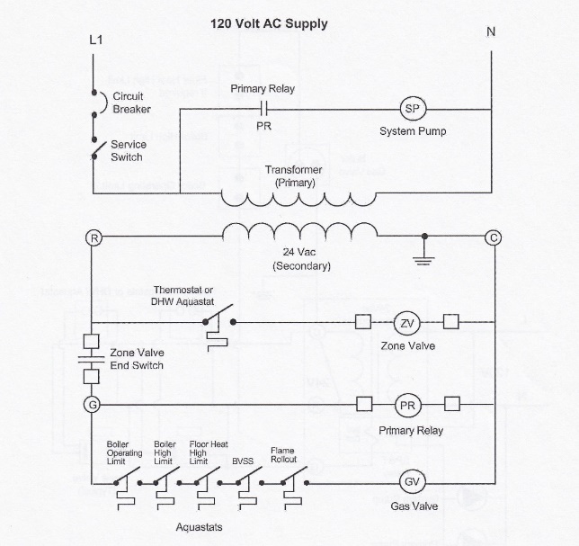
It is important to note that the schematic diagram tries to show the components as they might appear physically, whereas the ladder diagram shows only electrical symbols for the components. The schematic will have lines that cross each other on the page, and it may be hard to determine whether they are meant to connect or not. No wires in a ladder diagram will cross, so this diagram is sometimes easier to follow.
The transformer and relay for the diagrams above are shown contained within an enclosure known as a “furnace fan center” or “relay/transformer center”. Its original main use was to add control of air conditioning to an old furnace system that didn’t have a printed circuit board, but it also had use in hot water heating. It’s simply an electrical box with a cover plate that has fixed to it a transformer and a relay base that a specific relay plugs into. 120VAC is fed into the box where line voltage connections to the transformer and relay base are made. The 24VAC terminals are mounted on the face of the transformer as seen in the pictures below, and that is where all the low voltage connections are made.
As seen in the diagrams and picture above, the “R” terminal is the external power supply to the thermostats and end switches. The “C” terminal is connected internally to the neutral side of the 24VAC transformer and is also the external ground connection for the burner and zone valve circuits. The outlet side of the end switches are connected to the “G” terminal which feeds the internal relay coil and externally feeds power to the burner circuit.
If a relay/transformer center has “W” and “Y” terminals, as in the picture above, it is because it has another internal relay for control of other devices such as an air conditioning condenser and the furnace fan which would be set to high speed for cooling.
Today’s new residential hydronic systems are rarely single-temperature systems. Any RFPs (radiant floor panels) will be fed with water that is somewhere between 90°F and 140°F, depending on the BTUH/ft² required and the “R” value of floor coverings. Any non-condensing boiler used with RFPs will still be operated at 180°F – 200°F to prevent condensation caused by low return water temperatures, so a mixing means must be employed. Let’s look at 3-way mixing valves as an example of a popular way of achieving this result.
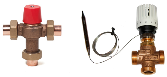
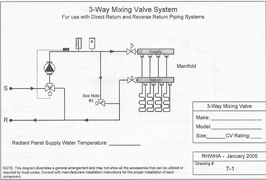
The position of the mixing stem in the valve on the left above is preset by hand and won’t therefore react to any change in temperature at the ports. The one on the right will find its position depending on the heat in the piping that the bulb is immersed in or strapped to and the heat setting on the dial. A motor and motor controller can also be used on 3-way valves if desired. The 3-way valve’s place in the piping system is shown below. Note that a mixing valve is located at the mixing point (the point in the piping system where the water is tempered), so it can have its sensor internally mounted.
The term “mixing valve” is used in a general context within the industry to denote the tempering of water through it.
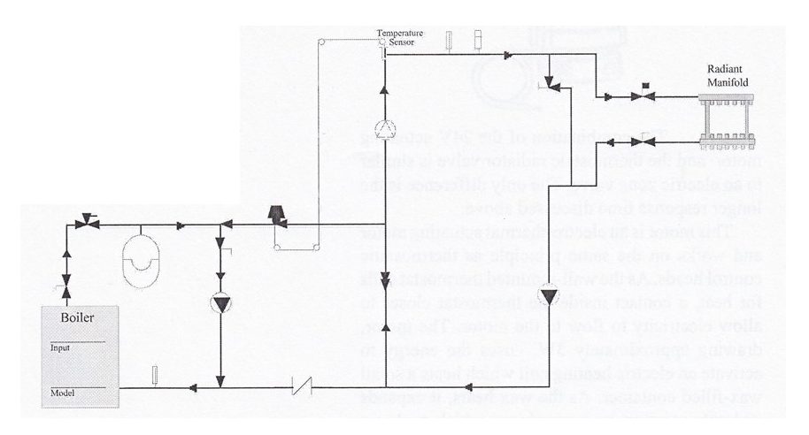
Diverting valves are also used for 3-way tempering, and are not installed in the same location as the mixing valves. See the diagram below.
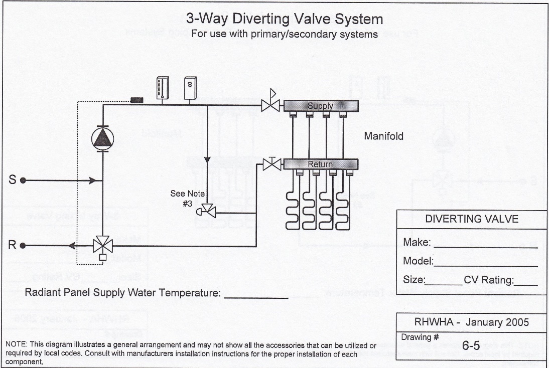
Diverting valves are mounted on the return piping, so they are not located at the mixing point; as such, they must have a remote means of measuring temperature. A bulb, strapped to the supply piping, must be used in order to make the diverting valve react to a change in temperature on a pipe that may be metres away from it.
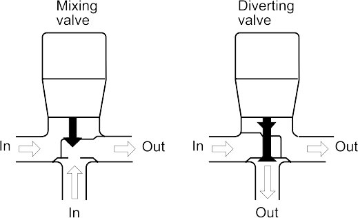
It is important to note that mixing and diverting valves are different, in that a mixing valve has two inlets and one outlet, whereas a diverting valve has one inlet and two outlets. Therefore, their use and positioning in a system is critical. Diverting valves are sometimes preferred because they have less head loss through them than mixing valves do.
A lesser-used component for tempering water in a circuit is by the use of a 2-way valve, as shown below.
The 2-way valve is simply a throttling valve with a low head loss that is controlled by a capillary tube connected to a bulb. The bulb is positioned to sense the temperature in the radiant circuit. These systems are very similar to primary/secondary piping in that hot system water is throttled through the 2-way valve from the main loop to adjust the temperature in the floor system. There is no hydraulic separation between the pumps, so much care must be exercised in their selection. 3-way and 4-way mixing systems are therefore seen to be a better choice.
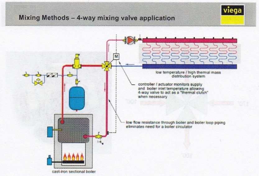
4-way mixing valves have very low head losses through them and as such, are considered the superior choice for tempering water.
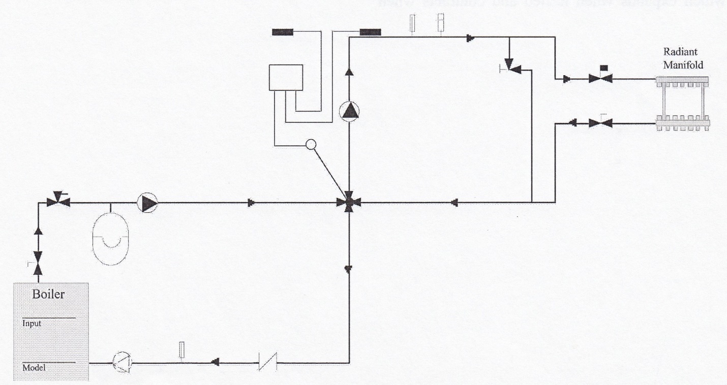
Just like the 3-way mixing and tempering valves, the 4-way valve can either be manually set to try to deliver one desired temperature or can be fitted with a motorized head which can automatically operate the mixing valve’s stem in reaction to both system water and outdoor air temperatures. This is known as “outdoor reset control”. As outdoor temperatures become colder, heat losses from a building increase. An outdoor reset control measures the outdoor temperature and as the indoor temperature drops, it balances the extra heat loss by making the system supply water hotter. A “heating curve” is used to calculate exactly how much hotter the supply water will need to be as outdoor temperature drops. The curve represents the number of degrees the supply water is raised for every degree the outdoor temperature falls. To calculate the correct heating curve, the following calculation is used.
Heating curve = (design supply temp − room temp) ÷ (room temp − outdoor design temp).
For example, if the ODT = 5°F, the desired room temperature = 70°F, and the desired design supply water temperature = 140°F, the calculation would be:
(140°F − 70°F) ÷ (70°F − 5°F) = 70°F ÷ 65°F = 1.08 (1.1)
This means that, for every 1°F drop in outdoor temperature, the system water temperature will increase by 1.1°F. Conversely, when the outdoor temperature rises to 70°F, the system will have reached a “thermal equilibrium” where indoor and outdoor temperatures are equal. The reset control will have reached its “warm weather shutdown point” (WWSD) and the heating system operation will not be necessary.
Outdoor reset control can also be applied to the boiler primary loop to allow a lower boiler supply temperature in all but the design times of the year, although in no case should the return water temperature be dropped below the atmospheric dew point if the boiler is of the non-condensing type.
The sensor for outdoor reset controllers should be mounted outside on the north face of the building where it doesn’t receive direct sunlight or is exposed to any heat/cold sources such as the discharge from a dryer vent.
Media Attributions
- Figure 1 Multiple temperature demands using on-demand modulating boiler © Viega. Used with permission.
- Figure 2 Temperature control using 4-way mixing for boiler protection © Viega. Used with permission.
- Figure 3 High temperature direct-return with indirect domestic water © Viega. Used with permission.
- Figure 4 Schematic diagram is courtesy of TECA BC.
- Figure 5 Ladder diagram is courtesy of TECA BC.
- Figure 6 Relay/transformer centre by ITA is licensed under a CC BY-NC-SA licence.
- Figure 7 Three-way mixing valves by ITA is licensed under a CC BY-NC-SA licence.
- Figure 8 3-way mixing valve placement is courtesy of TECA BC.
- Figure 9 3-way diverting valve placement is courtesy of TECA BC.
- Figure 10 3-way mixing and diverting valves by ITA is licensed under a CC BY-NC-SA licence.
- Figure 11 2-way injection valve placement is courtesy of TECA BC.
- Figure 12 4-way mixing system using outdoor reset control is courtesy of TECA BC.
