Learning Task 2
Describe Relays
What is a Relay?
Our electrical circuits in a residential hydronic heating system typically have two different voltage values. Motors for pumps, fans and hot surface igniters are usually powered with 120 volts of alternating current (120VAC). These devices need this amount of voltage to be able to operate efficiently. On the other hand, for the sake of safety and sensitivity, our control circuits are powered with 24 volts of alternating current (24VAC). One of the jobs that our 24VAC hydronic control systems have is to turn 120VAC pumps, igniters and fans on and off, and as such, creates a dilemma – if we connect a 24VAC control system directly to a 120VAC component, the higher voltage will overpower and wreak havoc on the lower voltage circuits and equipment. This is where and why relays are used. In a relay race, the contact between runners is made via a baton. It is passed from one runner to the other without the runners actually touching each other. Our electrical relays do much the same job. Low voltage can operate high voltage equipment, without the two touching each other, thanks to relays.
“EMR”s and “SSR”s
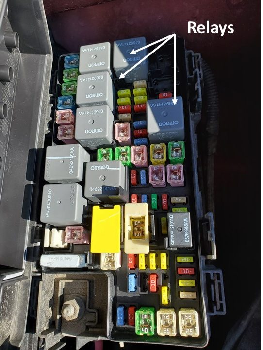
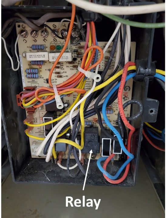
There are two varieties of relays: electromagnetic relays (EMRs) and solid-state relays (SSRs). They both do the same job, which is to use a circuit with low power to operate equipment that uses a higher-voltage power source. An SSR is silent in operation and has no moving parts within it, so there is no arcing across contacts that are opening and closing. Wear and tear isn’t an issue either and therefore an SSR has a lifespan of over 100 million cycles. EMRs, on the other hand, have a moving armature and moving contacts, and they will have a lifespan of roughly only 1 million cycles. Due to the arcing within them, EMRs can’t be used in a volatile environment whereas SSRs can. Although there are distinct advantages to SSRs, they tend to be limited to operating one circuit only, whereas an EMR can have multiple sets of contacts within it. SSRs are found on furnace and boiler modules, in solid state fuse and relay panels in vehicles, and PCBs (printed circuit boards) among other places.
Most of the relays that are used in hydronic systems, that aren’t a component of a PCB or solid-state control module, will be of the EMR type, so we will limit our study to EMRs.
Electromagnetic Relay Coils
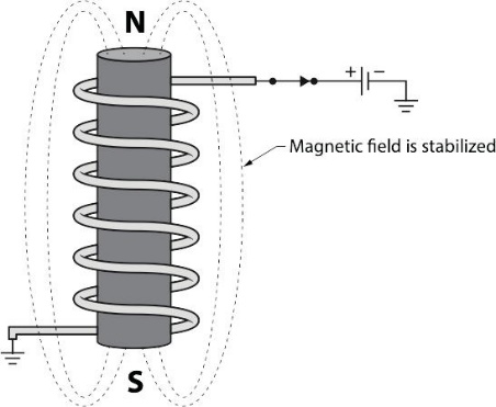
Relays consist of a temporary electomagnet known as a “coil” and a single or multiple sets of spring-loaded electrical contacts. Coils in electromagnetic relays are rated for the voltage that is to be supplied to them. In a hydronic heating control system that operates at 24VAC, the coil would also have to be rated for 24VAC. A coil is simply a soft iron bar that has a coil of wire wrapped around it, similar to the way in which a solenoid is built. The difference between them is that, unlike the coil of a solenoid, the soft iron core of the relay coil doesn’t move when it is energized. It becomes a temporary electromagnetic and is meant to attract an armature toward it.
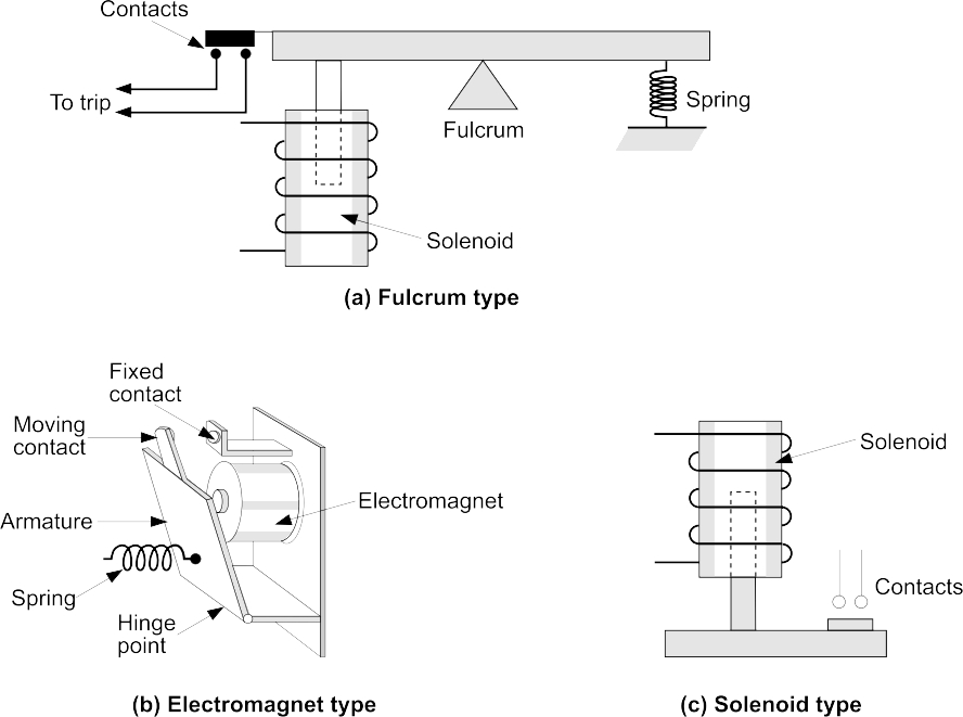
Attached to the armature is a ferrous component that will be attracted to the electromagnet, making it move. The armature itself doesn’t conduct any electricity but attached to it are contacts that do. If the relay contacts are N.O. they will close when the coil is energized. Any contacts that are N.C. will open at the same time. In short, when a relay coil is energized, an audible “click” can usually be heard, and the normal or “at rest” positions of any contacts it controls will reverse. When the coil is de-energized, an audible “click” will be heard as a spring pulls the armature back to its original position and the contacts are once again as they were before the coil was powered up. The diagram below illustrates the different ways that the armatures work.
The Contacts
On the schematic for the relay shown below, the dark black rectangles represent ¼” male spade terminals that poke through the housing of the relay and are points of connection to wires, while the light lines indicate how the terminals are connected to each other within the device. The terminals that connect to the coil are usually indicated by a symbol for the coil shown between them. The symbols that indicate whether a set of relay contacts are N.O. or N.C. are as indicated on the schematic. The relay contacts can be capable of voltage values of up to 600V or as indicated on that particular relay. As well, the contacts are capable of conducting either alternating current (AC) or direct current (DC) through them at the maximum amperages that are also indicated on the relay, usually on a printed tag affixed to the relay.
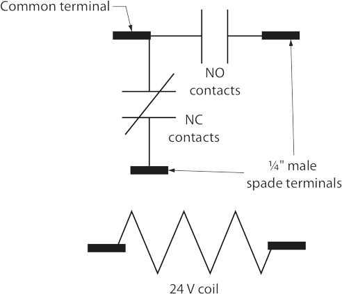
Below is a picture of a Honeywell DPDT relay that is very common to the heating industry. It is the type that the schematic above references, with the exception that the schematic is of a SPDT relay. The DPDT variety, as shown below, can control two circuits when the coil is energized whereas the SPDT only controls one.
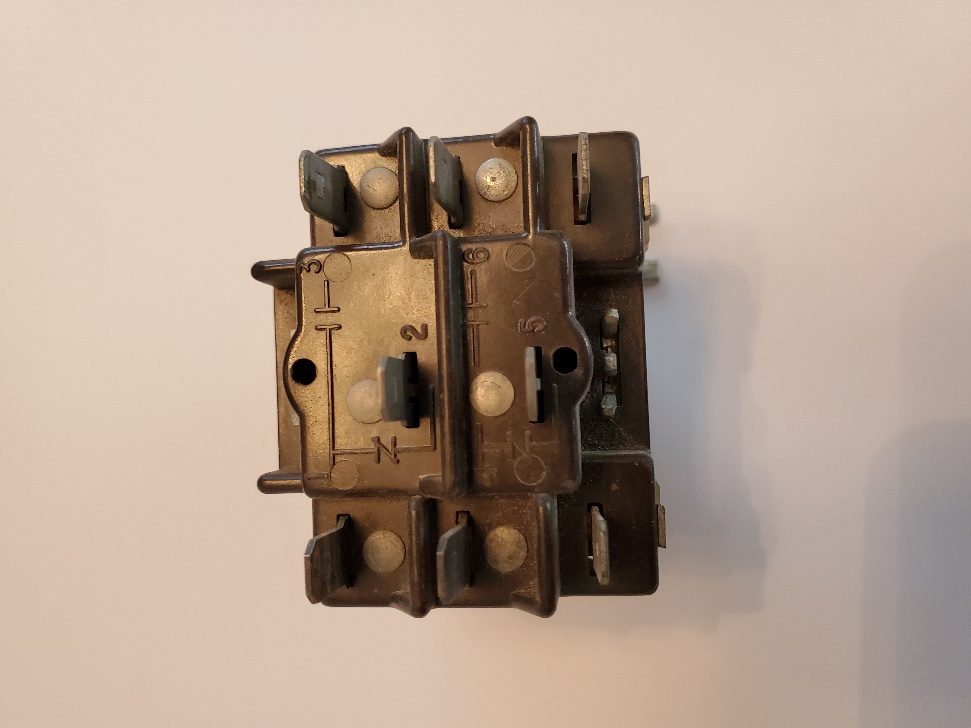
The relay pictured above has the wiring connections within its frame printed or cast into the plastic face as can be seen in the photo. The “common” terminal is #1 at the top left. This is where 120VAC would be connected if operating a 120VAC motor using the relay. The 120VAC output to the motor would be connected to terminal #3 at the top right (you should be able to see that there is a N.O. contact between them). When the coil is energized with 24VAC, the 120 volts, which was to this point present at terminal #2 (N.C.) is now directed to terminal #3 and the motor would be powered. Terminal #2 would be de-energized at this point.
Although not clearly marked on the face of the relay, the 24VAC coil is within the body of the relay, connected between the two bottom terminals shown.
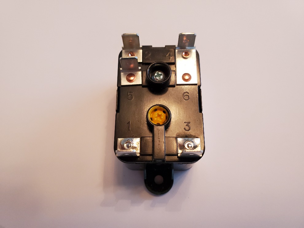
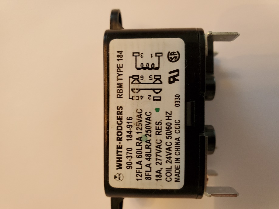
The relay pictured below would work in the same manner as the Honeywell relay above in that it has a 24VAC coil between terminals #1 and #3 at the bottom. The common terminal is #6 which is externally connected (“jumpered”) to #4 so any voltage applied to #6 would also exist at #4. Terminal #5 on the left has a N.C. connection between it and #6 as seen in the diagram below. This diagram is sometimes difficult to understand unless you are familiar with the concept of a relay. Terminal #2 on the top left has a N.O. connection between it and terminal #4. At rest, if there were voltage applied to terminal #6, it would also be present at terminal #5. When the coil across terminals #1 and #3 is energized with 24VAC, any voltage present at #5 would be interrupted and instead be diverted to terminal #2. This is where the hot line to a 120VAC motor would be connected.
In a 24VAC hydronic heating system, the relay allows a control voltage of 24VAC to turn on a 120VAC pump without the two voltages coming in contact with each other. A relay, therefore, is a magnetic switch, with electromagnetism being the force that operates the switching mechanism.
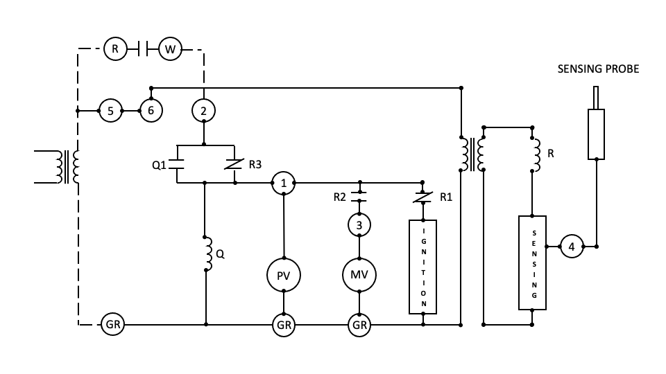
Many pieces of heating equipment have more than one relay, or multiple sets of relay contacts, and it may be necessary to identify and corelate the coils with the contacts they control. An industry standard is to number relay coils as 1K, 2K, 3K and so on. If relay 1K had 3 sets of contacts, then they would be labeled as 1K1, 1K2 and 1K3. Contacts for relay 3K would be labeled 3K1, 3K2, 3K3 etc. In that way, a wiring diagram with many relays and contacts should be easier to read and interpret, especially where diagnostics are concerned. The illustration below is of a supervisory control for gas equipment. It has a safe-start-check feature and can be followed by recognizing that there are 2 relay coils marked as “R” and “Q”. Relay coil “Q” only operates one set of contacts, being Q1 which is normally open (NO). Relay coil “R” has 3 sets of contacts, labeled as R1 (NC), R2 (NO) and R3 (NC). The drawing shows the system at rest, not yet operating. Leaving aside the sequence of operation, what we know is that when either coil is energized the contacts that it operates will reverse position. R1 and R3 will open when coil “R” is energized while R2 will close, and when coil “Q” is energized, contacts Q1 will close. Current flow will be stopped by any open contacts, and will flow across any contacts that are closed. Once the coils are de-energized they will snap back to their original position.
Now complete the Self-Test 3.
Self-Test 3
Self-Test 3
- What is the moving part of a switch known as?
- A contact
- A switch
- A throw
- A pole
- What is the stationary part of a switch known as?
- A contact
- A switch
- A throw
- A pole
- How are switches designated?
- By their numbers of poles and throws
- By their number of contacts and switches
- By their number of poles and moving parts
- By their number of moving parts and amperages
- What type of switch only “makes” while a person is pushing or twisting it?
- A time delay switch
- A short-term switch
- A momentary switch
- An instantaneous switch
- Which one of the flowing choices would most accurately describe a heating thermostat?
- A pressurestat
- Open on rise
- Close on rise
- A relay
- What are switches called that react to water temperature?
- Pressurestats
- Thermostats
- Flowstats
- Aquastats
- What does this symbol represent?
- A flow switch
- A level switch
- A pressure switch
- A temperature switch
- What is the name of the switch that is used in a zone valve to prove that the valve is open?
- A limit switch
- A proving switch
- A low water cutoff
- An end switch
- What voltage value is applied to the two yellow wires of most zone valves?
- 24V DC
- 24V AC
- 120V DC
- 120V AC
- What voltage value is applied to the two red wires of most zone valves?
- 24V DC
- 24V AC
- 120V DC
- 120V AC
- In which leg of a circuit should switches be located?
- The neutral leg
- The hot leg
- The cold leg
- The grounded leg
- What type of relay is most often found in use in hydronic heating systems?
- SSR
- ECM
- MMA
- EMR
- What is the voltage value of the coil in most relays used in hydronic heating control circuits?
- 24V DC
- 24V AC
- 120V DC
- 120V AC
- What voltage value do most pumps in hydronic systems use?
- 24V DC
- 24V AC
- 120V DC
- 120V AC
- Which one of the following statements regarding EMRs would be correct?
- When the coil is energized, only the NO contacts will open
- When the coil is energized, only the NC contacts will close
- When the coil is energized, the contact positions will reverse
- When the coil is energized, it will transform 120VAC into 24VAC
- What would the device to the right be called?

- A relay coil
- A DPDT switch
- A relay contact
- A SPDT switch
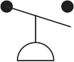
- What would the device below be called?
- A pressure switch
- A low water cutoff
- A momentary switch
- A pressure relief valve
- What is the device shown below?
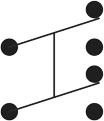
- A SPDT switch
- A DPST switch
- A DPDT switch
- A momentary switch
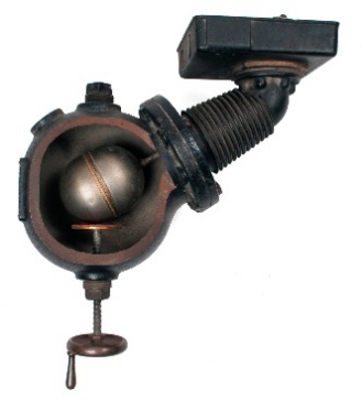
- What is the device pictured?
- A low water cutoff
- A flow switch
- A pressure switch
- An aquastat
- Which variety of relay has no moving parts but usually only controls one device?
- An EMR
- An MMA
- An ECM
- An SSR
Check your answers using the Self-Test Answer Keys in Appendix 1.
Media Attributions
- Figure 1 SSRs in a vehicle’s fuse panel by ITA is licensed under a CC BY-NC-SA licence.
- Figure 2 SSR on an integrated furnace control board by ITA is licensed under a CC BY-NC-SA licence.
- Figure 3 Temporary electromagnet (coil) by ITA is licensed under a CC BY-NC-SA licence.
- Figure 4 Relay coils and armatures by ITA is licensed under a CC BY-NC-SA licence.
- Figure 5 Honeywell SPDT 24VAC relay by ITA is licensed under a CC BY-NC-SA licence.
- Figure 6 Honeywell DPDT relay with 24VAC coil by ITA is licensed under a CC BY-NC-SA licence.
- Figure 7 White-Rodgers 24VAC SPDT relay by ITA is licensed under a CC BY-NC-SA licence.
- Figure 8 Schematic on side of White-Rodgers relay by ITA is licensed under a CC BY-NC-SA licence.
- Figure 9 Wiring schematic diagram showing relay coils and their contacts by ITA is licensed under a CC BY-NC-SA licence.
