Part 7
Module 36: Competency Test 7 Open Book
Learning Outcomes
When you have completed this module, you will be able to:
- Within a three hour time limit, complete a written exam and the lab exercise without the aid of a key.
The AutoCAD 2D book was written with competency based modules. What that means is that you have not completed each module until you have mastered it. The Competency Test module contains multiple choice questions and a comprehensive lab exercise to test your mastery of the set of modules that you completed. There are no answers or keys supplied in a Competency Test module since it is meant to be checked by your instructor. If there are any parts of this module that you have trouble completing, you should go back and reread the module or modules containing the information that you are having trouble with. If necessary, redo as many lab exercises required until you fully understand the material.
If you are Completing this book:
- Without the Aid of an Instructor, complete the written test and the lab exercise.
- In a Classroom with an Instructor, the instructor will give instructions on what to do after this module has been completed.
Multiple Choice Questions
Select the BEST answer.
- What term is used to describe a block within block?
- Nested object
- Hatched object
- Xref object
- Bound object
- Insert object
- What command is used to establish a block’s base point?
- XREF
- BLOCK
- INSERT
- PEDIT
- POINT
- Where are block definitions stored in a drawing’s database?
- Block location table
- Block definition table
- Block database table
- Block table
- Block database
- What command is used to edit existing hatch patterns?
- EDITHATCH
- BHATCH
- EDIT
- PEDIT
- HATCHEDIT
- From what drawing object are all hatch patterns created from?
- Plines
- Arcs
- Lines
- Splines
- None of the above.
- What command is used to totally remove a block definition from the current drawing?
- TAKEOUT
- PURGE
- DELETE
- REMOVE
- BLOCK
- What command is used to change the name of a block definition in the current drawing?
- INSERT
- NAME
- CHANGE
- RENAME
- PURGE
- What must be done to completely remove a reference file from the current drawing?
- Detach it using the XREF command.
- Detach it using the XBIND command.
- Erase it using the ERASE command.
- Detach it using the BLOCK command.
- Detach it using the BIND command.
- What two commands are used to toggle the display of the existing hatching patterns on or off?
- FILL and EXPLODE
- PEDIT and FILL
- REGEN and PEDIT
- EXPLODE and FILL
- FILL and REGEN
- When a reference file is bound to a drawing that it is attached to, what drawing object type is the xref converted into?
- Individual objects
- Line
- Block
- Pline
- Hatch
Lab Exercise 36-1 OPEN BOOK
| Drawing Name | Template | Units |
|---|---|---|
| AutoCAD 2D Lab 36-1 | N/A | Feet and Inches |
Step 1
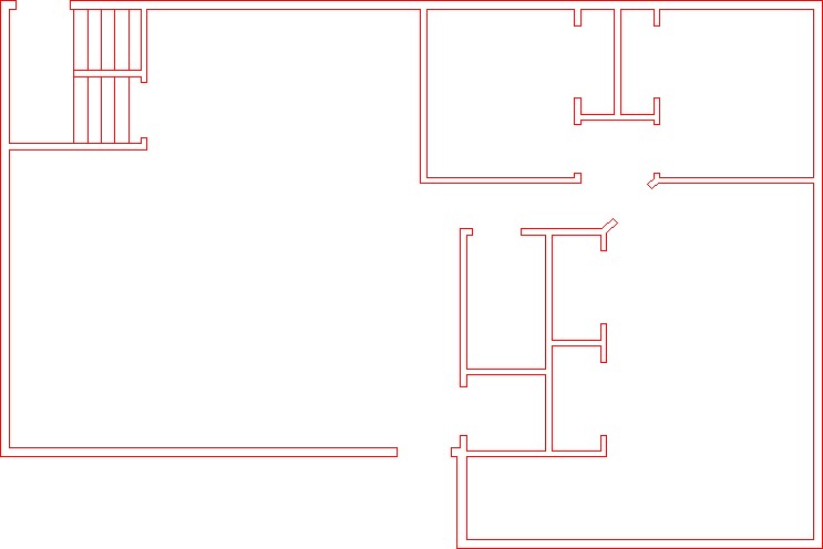
Open the drawing: AutoCAD 2D Lab 29-3. (Figure Step 1)
Step 2
Using the SAVEAS command, save the drawing with the name: AutoCAD 2D Lab 36-1.
Step 3
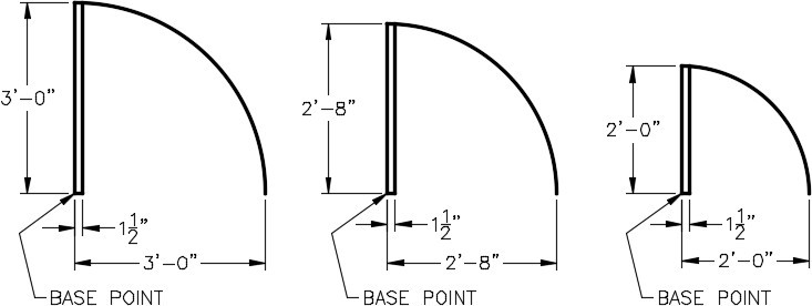
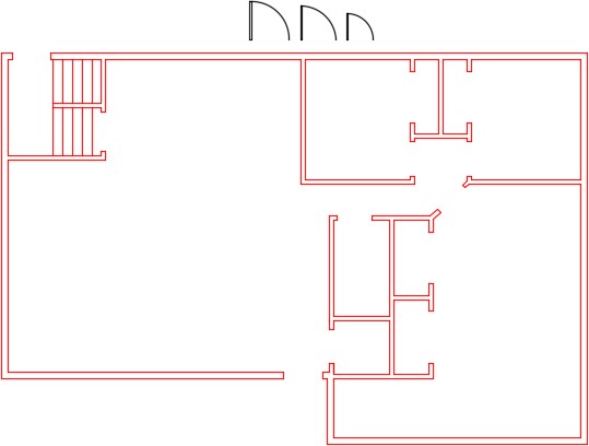
Draw the three doors, shown in the figure, anywhere in Model space. Draw them on layer: 0. Ensure that the color assigned to layer: 0 is black/white. (Figure Step 3A and 3B)
Step 4
Create a block from each of the three doors that you drew in Step 3. Use the following:
A Name each block as shown below the drawing.
B Set the BLOCK command to delete the objects after creation.
C Set the base point of the blocks as shown on the drawing.
D Give each block a description and set the Block units to Inches.
Step 5
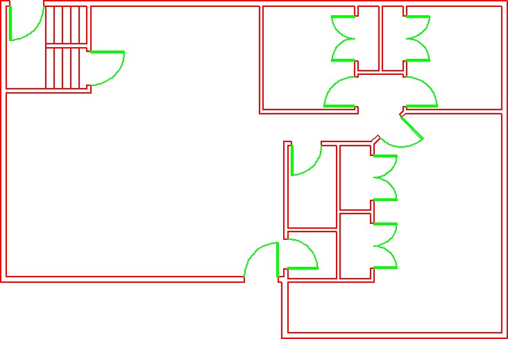
On layer Doors, insert the door blocks to match the door opening size. (Figure Step 5)
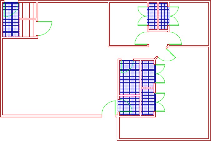
Step 6
On layer Hatch, insert the pattern: Net in the areas shown in the figure. Set the scale to match the hatch to the figure the best you can by eye. (Figure Step 6)
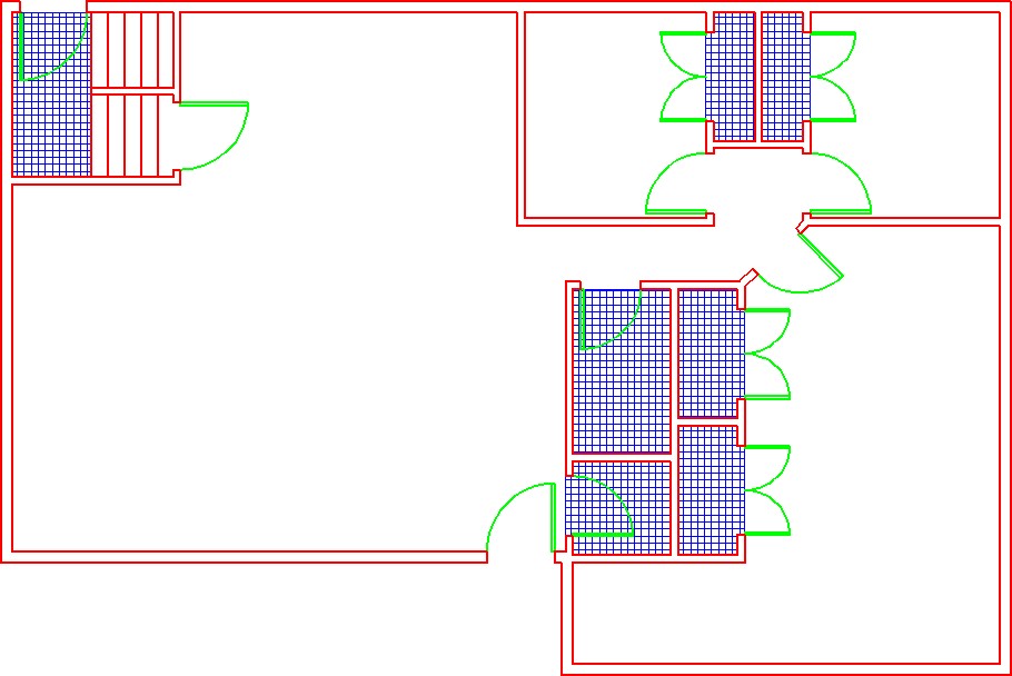
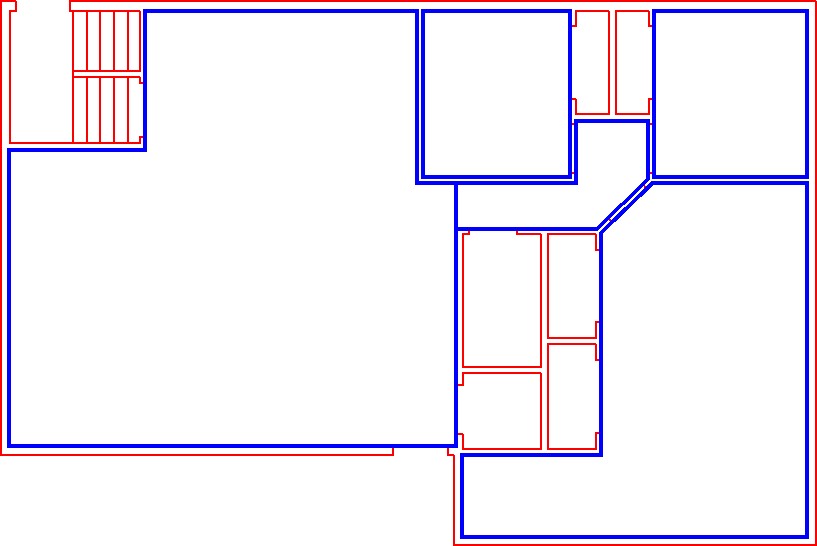
Step 7
On layer: Boundary, draw a closed pline, at a width of 1″, around the 4 rooms and the hallway. Ensure that you snap to the corners of the walls. Find the area of each closed pline in Sq Ft to two decimal places of precision. Record the results. (Figure Step 7)
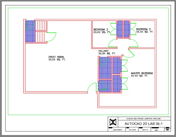
Step 8
Enable layout: Module Layout C. On layer: Viewport, create a viewport at a scale of 3/8″=1′-0″ and lock the display. In Paper space, on layer: Text, add the room name and square footage that you found in Step 7. Using the standards in Module 20, fill in the titleblock. (Figure Step 8)
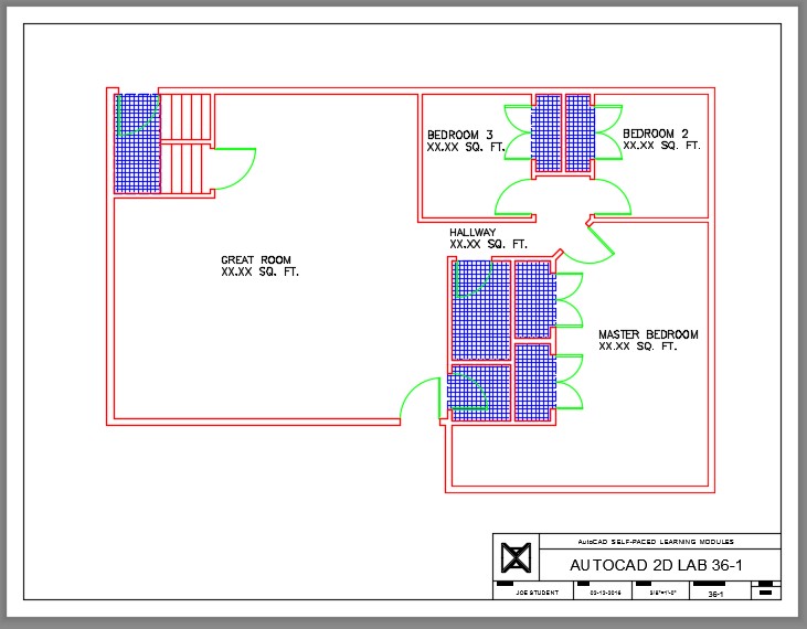
Step 9
Turn layers: Viewport and Boundary off to complete the drawing. (Figure Step 9)
Step 10
Change the current space to Model. You drawing should match the figure. (Figure Step 10)
Step 11
Saved and close the drawing.
