Part 7
Module 34: Drawing Utilities
Learning Outcomes
When you have completed this module, you will be able to:
- Explain drawing and file maintenance to help manage and control AutoCAD drawing files.
- Describe a nested object.
- Apply the TIME, PURGE, and RENAME commands.
Drawing Utilities
It is very important for you as the AutoCAD Operator to maintain your drawings and drawing files on a regular basis. It is very easy, while working day-to-day producing drawings, to let things slide and not correct small items in the drawings or the drawing files. If left unchecked, this habit can lead to a large problem in the future, sometimes almost impossible to correct.
Take a few minutes, while working on each drawing, to maintain objects, layers, blocks, xref, names, and the different styles. For the drawing files, create an organized logical folder structure making more folders rather than less and dividing drawing files into smaller organized groups. Create a good naming system for the folders and drawings. Give them descriptive names that can be sorted alphabetically. Remove unwanted files, and keep your .bak files under control by deleted ones that are no longer required.
AutoCAD has several utilities that are helpful to organize and maintain drawings. File Explorer can be used to maintain the drawing files. In this module, the PURGE and RENAME commands are covered to help you in your day-to-day drawing maintenance.
Nested Objects
A nested object is a named object referencing another named object. One example of a nested object would be an object in a block located on layer Object but the block is on layer Block. The Object layer would appear not to have any objects on it, but in fact, an object in the block is on that layer and that makes it a nested object. Sometimes it is desirable to nest items to help draw and design more efficiently. An example of this is as follows: A drawing has several components. Draw each component separately and create a block of each. Assemble all the blocks and then make a block of the assembly. The blocks inserted in the assembly block are nested blocks. Nested objects are not necessarily a bad thing, but they can cause problem if they are not used correctly or carelessly inserted.
AutoCAD does not allow a block to be created using a block that references itself. An example of this would be a block created using an object that contains a block with the same name. One the most common errors in block creation is creating a block selecting a block as one of the selected objects. Ensure that all drawing objects are exploded before creating a block using them.
AutoCAD Command: TIME
The TIME command is used to display and track the amount of time that a drawing file is opened in AutoCAD.
Shortcut: none
AutoCAD Command: PURGE
The PURGE command is used to remove block definitions, dimension styles, groups, layers, linetypes, text styles, zero-length geometry, and empty text objects.
Shortcut: PU
AutoCAD Command: RENAME
The RENAME command is used to rename such things as block definitions, dimension styles, layers, linetypes, text styles, UCS’s, viewports, and views.
Shortcut: REN
WORKALONG: Using the TIME, PURGE and RENAME Commands
Step 1
Start a new drawing using the template: 2D Layout English.
Step 2
Save and name the drawing: AutoCAD 2D Workalong 34-1.
Step 3
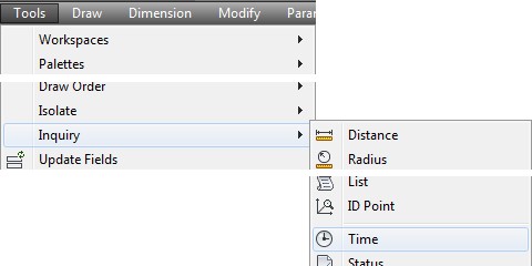
Enter the TIME command, as shown below.
Command: TIME
Current time: Wednesday, March 01, 2016 11:49:30:937 AM
Times for this drawing:
Created: Wednesday, March 01, 2016 11:48:42:453 AM
Last updated: Wednesday, March 01, 2016 11:48:42:453 AM
Total editing time: 0 days 00:12:48:672
Elapsed timer (on): 0 days 00:12:48:484
Next automatic save in: 0 days 00:09:13:172
Enter option [Display/ON/OFF/Reset]:
Command:
Step 4
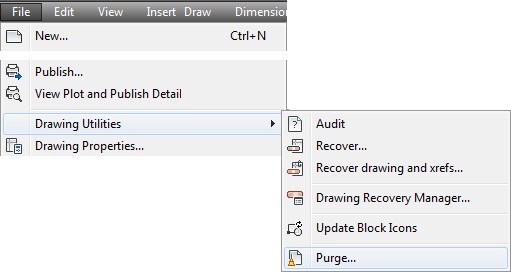
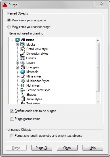
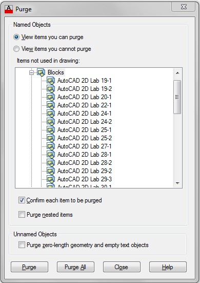
Enter the PURGE command. It will open the Purge dialogue box. (Figure Step 4)
Step 5
Ensure that the View items you can purge is enabled. (Figure Step 5)
You can only purge items from a drawing if they are NOT being used at the time. For example, an item that CAN be purged is a block that is defined but is not inserted in the drawing or a layer that was created but does not contain any objects. The items that can be purged will display with a + (plus sign) preceding them.
Step 6
Expand All items and then Blocks by clicking the + (plus sign) preceding each. When you see the – (minus sign), the item is expanded and will display all of the items that can be purged. All of the blocks in the Block Definition table that are NOT inserted in the drawing will display. (Figure Step 6)
Step 7
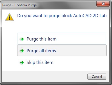
Select the item Blocks. Click the Purge All button. When asked to confirm the purging, click Purge all items. (Figure Step 7)
Step 8
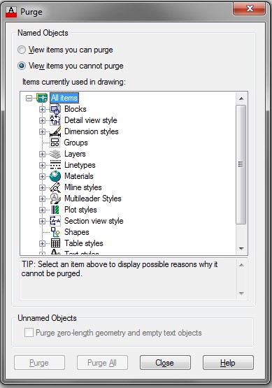
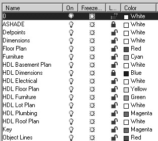
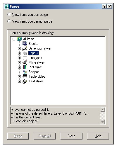
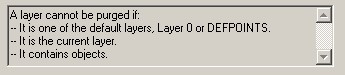
Enable the View items you cannot purge button. The items that you CANNOT purge will display in the Purge dialogue box. (Figure Step 8A and 8B)
Step 9
Close the dialogue box. Enter the TIME command as shown below.
Command: TIME
Current time: Wednesday, March 01, 2016 2:04:49:703 PM
Times for this drawing:
Created: Wednesday, March 01, 2016 1:21:07:562 PM
Last updated: Wednesday, March 01, 2016 1:21:07:562 PM
Total editing time: 0 days 15:43:42:157
Elapsed timer (on): 0 days 15:43:42:141
Next automatic save in: 0 days 00:07:33:123
Enter option [Display/ON/OFF/Reset]: R
(Reset the timer to zero. This is an elapsed timer which allows you to time a special event while the total time the drawing is active is also being timed.)
Enter option [Display/ON/OFF/Reset]: D
(The Display option simply forces the command line to display the time values.)
Current time: Wednesday, March 01, 2016 2:05:08:312 PM
Times for this drawing:
Created: Wednesday, March 01, 2016 1:21:07:562 PM
Last updated: Wednesday, March 01, 2016 1:21:07:562 PM
Total editing time: 0 days 00:44:00:766
Elapsed timer (on): 0 days 00:00:08:437 Next automatic save in: 0 days 00:07:33:123 Enter option [Display/ON/OFF/Reset]:
Command:
Step 10
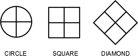
On layer: 0, draw the three objects shown in the figure. Draw the circle 1 inch in diameter and the length of each side of the square and the diamond 1 inch. The location where you draw them is not important. (Figure Step 10)
Step 11
Create three blocks, one from each object, and name them: Circle, Square, and Diamond respectfully. Delete the drawing objects when you create the block for each. After you have created all three blocks, your drawing should appear blank.
Step 12
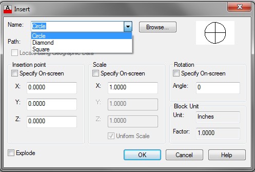
Check to ensure that the blocks were created by entering the INSERT command. In the list of names, you should only see the three blocks. (Figure Step 12)
Step 13
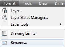
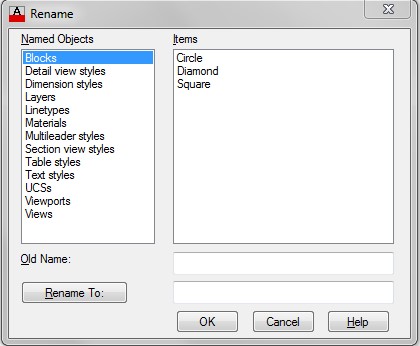
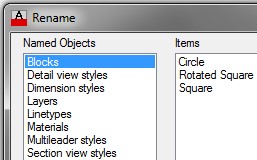
Enter the RENAME command. It will open the Rename dialogue box. Select Blocks in the Named Objects column. The three blocks you created in Step 11 will display in the Items column. (Figure Step 13)
Step 14
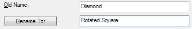
Click the block: Diamond in the Items column. Note how it now appears in the Old Name: box. Enter the new block name: Rotated Square in the Rename To: box. Click the Rename To: button to execute the name change. The renamed block will now appear in the Items box. (Figure Step 14A and 14B)
Step 15
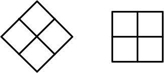
Using the INSERT command, insert the blocks: Square and Rotated Square. The location where you insert them is not important. Your drawing should appear as shown in the figure. (Figure Step 15)
Step 16
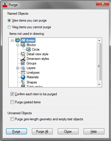
Enter the PURGE command. In the Purge dialogue box, enable View items you can purge. Expand the item Blocks and the Circle block should display as shown in the figure. (Figure Step 16)
Step 17
Using what you learned earlier in this workalong, purge the block: Circle from the drawing.
Step 18
Enter the TIME command as shown below. Command: TIME
Currenttime: Wednesday, March 01, 2016 2:30:21:015PM
Times for this drawing:
Created: Wednesday, March 01, 2016 1:21:07:562 PM
Last updated: Wednesday, March 01, 2016 1:21:07:562 PM
Total editing time: 0 days 01:09:13:485
Elapsed timer (on): 0 days 00:25:21:156
Next automatic save in: 0 days 00:02:58:672
Command:
Step 19
Find the record the following answers in your drawing:
A Total editing time in the drawing.
B Time in Elapsed timer.
Step 20
Save and close the drawing.
Drafting Lesson: Cross Sections – Part 2
Types of Section Views
There are many types of section views that can be drawn. The full, half, aligned and revolved section, as shown in figures below, are the most common ones.
Full Section
A full section is the most commonly used cross section. It cuts completely through the object along the cutting plane. See Figure 35-1.
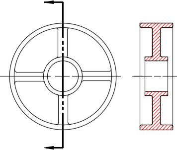
Full Section
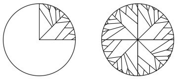
Half Section
The half section only cuts through half of the object. It is used to section a symmetrical object where both halves are identical. See Figure 35-2.
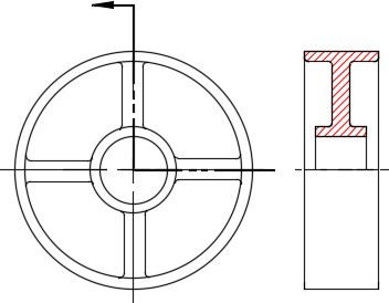
Half Section
Aligned Section
An aligned section is used to align spokes along the cutting plane on a symmetrical object. Take note how the spokes are not on the cutting plane but are aligned in the section view. See Figure 35-3.
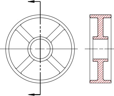
Aligned Section
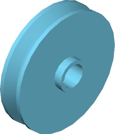
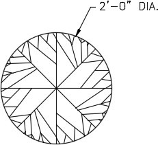
Revolved Section
A revolved section is a simple way to show the shape of an object i.e. A spoke. Revolve the section on the object as shown in Figure 35-4.
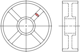
Revolved Section
Key Principles
Key Principles in Module 34
- The PURGE command removes unwanted items from the drawing. In some cases, it is the only way to remove them. If an item is being used, it cannot be purged.
Lab Exercise 34-1
Time allowed: 60 minutes.
| Drawing Name | Template | Units |
|---|---|---|
| AutoCAD 2D Lab 34-1 | 2D Layout Metric | Millimeters |
Step 1
On layers: Object and Hidden, draw the Front and Right Side view as shown in the figure. (Figure Step 1A and 1B)
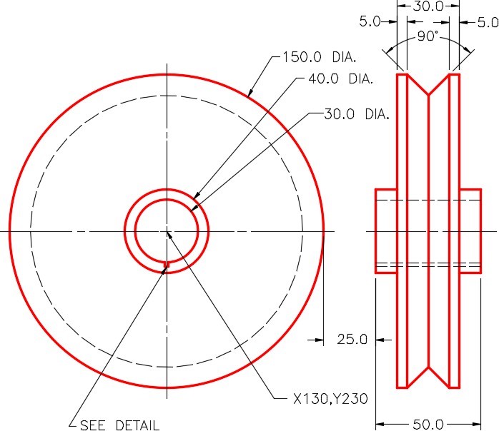
Completed Drawing
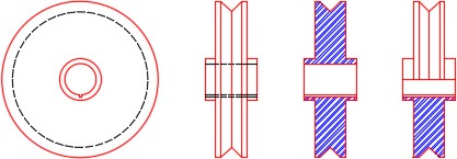
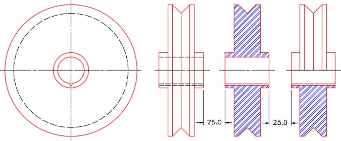
Step 2
On layers: Object and Hatch, draw a full section and a half section. Use hatching pattern: ANSI32. Select an appropriate scale to match the figure the best that you can. (Figure Step 2A and 2B)
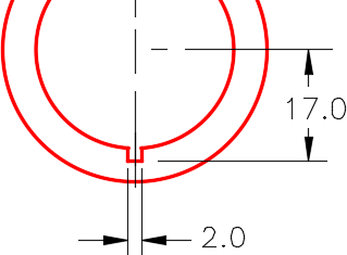
Detail of Key
Hint 1
To help you visualize the object that you are drawing. (Figure Step 1A and 1B)
Solid Model
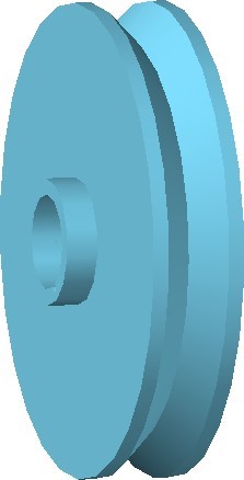
Solid Model
Lab Exercise 34-2
Time allowed: 30 minutes.
| Drawing Name | Template | Units |
|---|---|---|
| AutoCAD 2D Lab 34-2 | N/A | Feet/Inches |
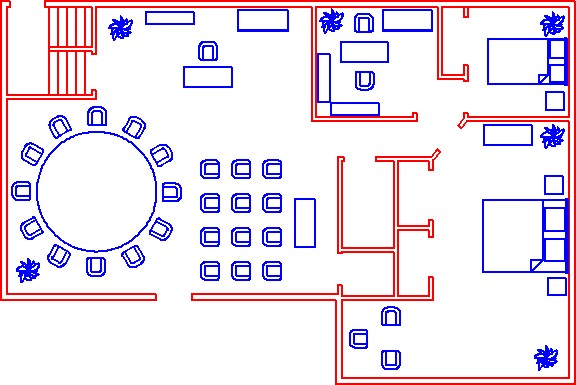
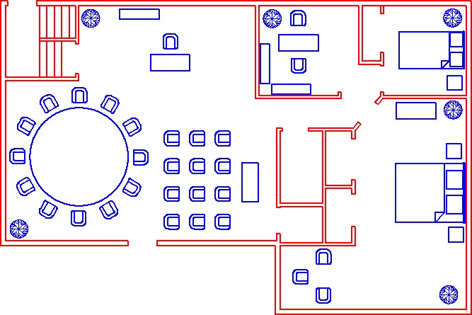
Step 1
Open the drawing: AutoCAD 2D Lab 33-1. (Figure Step 1)
Step 2
Using the SAVEAS command, save the drawing with the name: AutoCAD 2D Lab 34-2.
Step 3
Reset the elapsed timer to zero.
Step 4
Delete all existing blocks named: File Cabinet that are on the drawing. (Figure Step 4)
Step 5
Purge the block: File Cabinet from your drawing.
Step 6
Rename the following blocks:
A From: Desk to 48X28 Desk
B From: Conference Table to 10 Ft. Diameter Table
Step 7
On layer: 0, draw the plant shown in the figure. (Figure Step 7A and 7B)
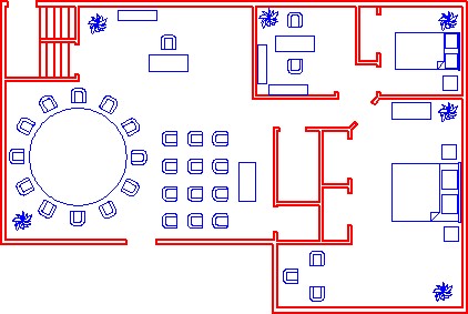
Step 8
Redefine the block in the drawing named: Plant with the plant you drew in Step 7. All existing plant blocks should change to the new plant block. (Figure Step 8)
Step 9
Using the elapsed timer, record the amount of time you took to do this lab exercise.
Step 10
Save and close the drawing.
