Part 6
Module 28: Grids and Snap
Learning Outcomes
When you have completed this module, you will be able to:
- Describe grids and snap and explain how they are used in a drawing.
- Apply the commands GRID and SNAP to create a drawing.
- Create a three view multiview drawing from a 3D wireframe model.
- Describe how to create a three point arc by snapping to two endpoints and a midpoint.
USER TIP: Whenever possible, use the keyboard function keys to toggle features rather than using the Status bar or the applicable commands. Using a function key to toggle a feature is a much faster method and will save the wear and tear on your mouse arm. The function keys that you have learned to this point in the book are:
![]()
Using Grids and Snap
Grids are a series of dots or lines that display and overlay the Graphic window in a rectangular or square shape similar to overlaying a paper drawing with grid paper. Grids do not plot and are not part of the drawing’s database, they are simply a drawing aid.
The grid can be set to display using dots or lines. See Figures 28-1 and 28-2. The grid’s density can be adjusted and their display can be enabled or disabled, when required. The horizontal and vertical spacing between the grid dots or lines can be different, but by default are equal. The grid display can be toggled with the F7 key, the icon on the Status bar, with the GRID command, or by using the Drafting Settings dialogue box. The size of the rectangle that the grid fills can be set to the size of the drawing limits or it can be set to fill Model space. Grids can also be displayed in a layout in Paper space.
A Grid Using a Dotted Grid
The snap feature works in conjunction with grids. If snap is enabled, the crosshairs snaps only to grid dots, similar to object snap mode. The grid density and the snap density do not have to be set at the same value. Therefore, the crosshairs could snap to locations between the displayed grid dots. The snap can be toggled using the F9 key, with the icon on the Status bar, using the SNAP command, or with the Drafting Settings dialogue box. If snap is enabled, it snaps to the snap density even if the grid display is disabled.
A Grid Using a Lined Grid
AutoCAD Command: GRID
The GRID command is used to display a series of dots or lines in either an equal or unequal horizontal and vertical spacing. The function key F7 toggles grid mode.
Shortcut: F7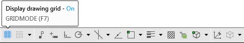
AutoCAD Command: SNAP
The SNAP command is used to control and enable the snap feature. The function key F9 toggles snap mode.
Shortcut: F9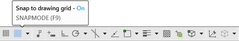
WORKALONG: Using Grids and Snaps
Step 1
Start a new drawing using the template: 2D Layout English.
Step 2
Save and name the drawing: AutoCAD 2D Workalong 28-1.
Step 3
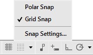
Open the Drafting Setting dialogue box by right clicking the Snap icon in the Status bar and clicking Snap Settings. (Figure Step 3)
Step 4
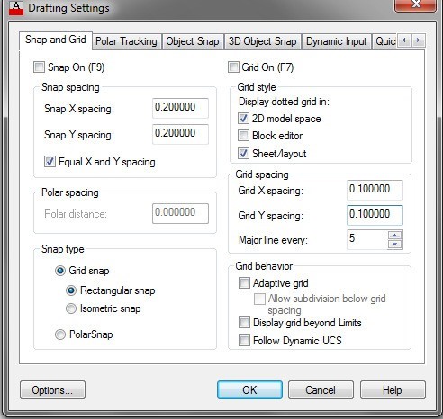
In the Drafting Setting dialogue box, enable the Snap and Grid tab. Set the X and Y snap and grid spacings to 0.2 and 0.1 respectfully. Check all of the other settings and change them, if necessary, to match the figure. (Figure Step 4)
Step 5
Enter the LIMITS command, as shown below, to set the limits to 8 1/2 X 11 inches.
Command: LIMITS
Reset Model space limits:
Specify lower left corner or [ON/OFF] <0.0000,0.0000>:
Specify upper right corner <12.0000,9.0000>: 8.5,11
Command:
Step 6
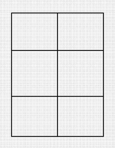
Press F7 to enable the grid display and your drawing should appear similar to the figure. (Figure Step 6)

MUST KNOW: If you find your crosshairs jumping around your screen and hard to control, check to see if the snap icon is enabled on the Status bar. Some menu commands will toggle snap mode without you knowing it. Disable snap whenever you are not using it.


Keep in mind that you can toggle the snap with F9 or by clicking the icon on the Status bar.
Step 7
Press F9 to enable the snap function.
Step 8
On layer: Construction, enter the LINE command and draw lines as shown in the figure. Locate and draw the lines by eye. Try to match the figure the best you can. (Figure Step 8)
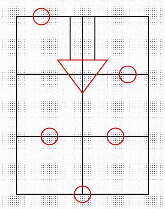
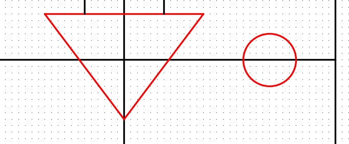
Step 9
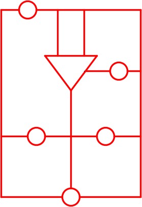
On layer: Object, use the CIRCLE and LINE commands to draw the 5 circles and three lines to form the triangle. Use the detailed figure (Figure Step 9B) to size the circles and the triangle. Snap to grid dots to draw all objects. (Figure Step 9A and 9B)
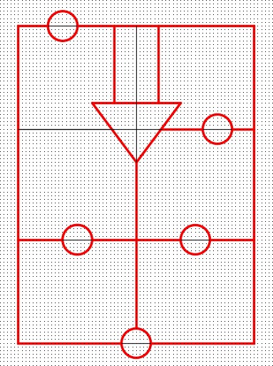
Step 10
On layer: Object, use the LINE command to draw the lines as shown in the figure. Snap to the grid dots for all lines. (Figure Step 10)
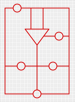
Step 11
Turn layer: Construction off and trim the any necessary lines. (Figure Step 11)
Step 12
Press F7 and F9 to disable the grid and the snap functions. (Figure Step 12)
Step 13
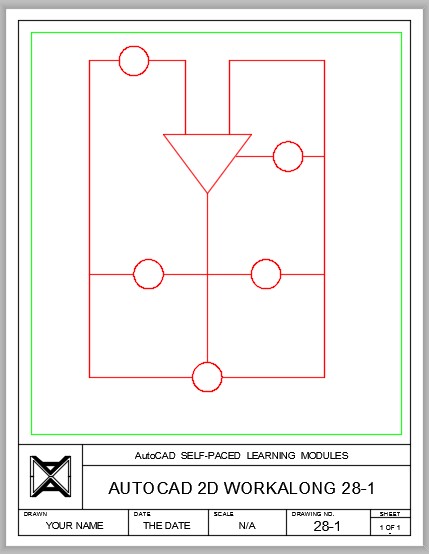
On layout: Module Layout A, create a viewport on layer: Viewport. Set the scale of the viewport to 0.75:1 and lock the display. Complete the titleblock using the AutoCAD book Titleblock Standards shown in Module 20. (Figure Step 13)
Step 14
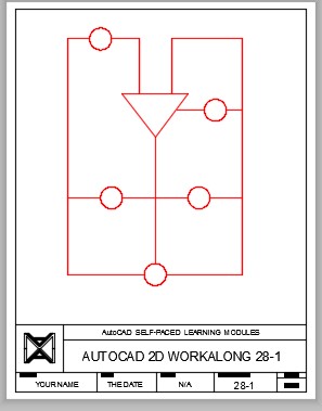
Turn layer: Viewport off. (Figure Step 14)
Step 15
Save and close the drawing.
WORKALONG: Using Ortho Mode as an Aid to Draw a Multiview Drawing
Step 1
Start a new drawing using the template: 2D Layout Metric.
Step 2
Save and name the drawing: AutoCAD 2D Workalong 28-2.
Step 3
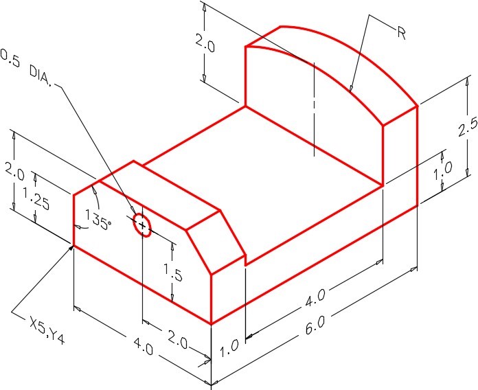
Set layer: Object as the current layer. Study the figures. (Figure Step 3A, 3B, and 3C)
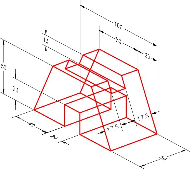
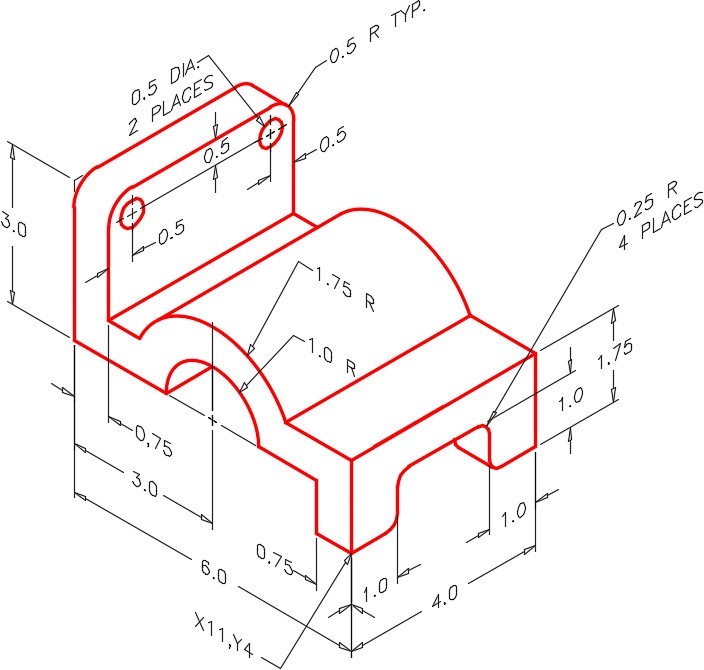
Dimensioned Wireframe Model
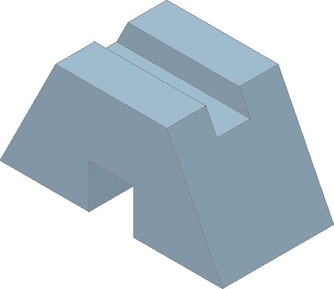
Solid Model
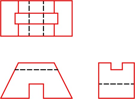
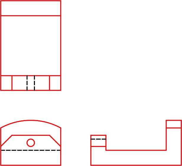
Multiview Drawing
Step 4
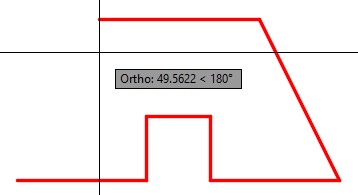
Enable Ortho mode by pressing F8. Draw the Front view by entering the LINE command shown below. (Figure Step 4A to 4H)
Command: L
Specify first point: 100,100
(Move the crosshairs in the positive X direction.)
Specify next point or [Undo]: 40
(Note how you only have to enter the X distance. As long as Ortho mode is enabled, you are not required to enter the @.)
(See Figure Step 4A)
(Move the crosshairs in the positive Y direction.)
Specify next point or [Undo]: 20
(See Figure Step 4B)
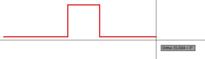
(Move the cursor in the positive X direction.)
Specify next point or [Undo]: 20
(See Figure Step 4C)
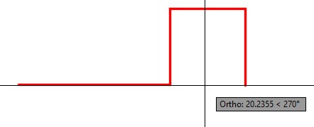
(Move the crosshairs in the negative Y direction.)
Specify next point or [Undo]: 20
(See Figure Step 4D)
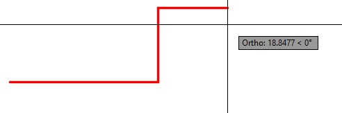
(Move the crosshairs in the positive X direction.)
Specify next point or [Undo]: 40
(See Figure Step 4E)
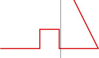
Specify next point or [Undo]: @-25,50
(The crosshairs position is not important when you enter exact coordinates. Ortho mode will be ignored when both coordinates are entered. See Figure Step 4F)
(Move the crosshairs in the negative X direction.)
Specify next point or [Undo]: 50
(See Figure Step 4G)
Specify next point or [Close/Undo]: C
(Close the line to the start point. Figure Step 4H)
Specify next point or [Close/Undo]:
Command:

Step 5
On layer: Construction, with Ortho mode and Osnap mode enabled, use the LINE command to draw a vertical line by snapping the first point to the end of the bottom line. The length of the line is not important. (Figure Step 5)

Step 6
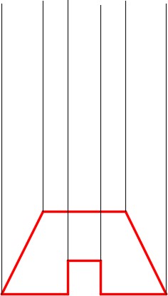
Using what you just learned, repeat the same thing five additional times to draw vertical lines from each endpoint on the front view. (Figure Step 6)
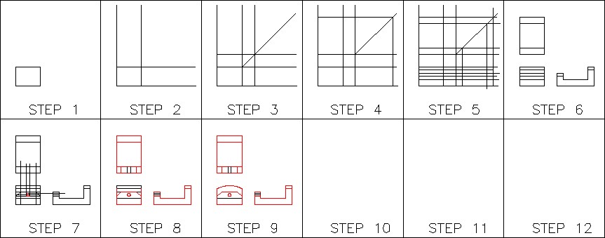
Step 7
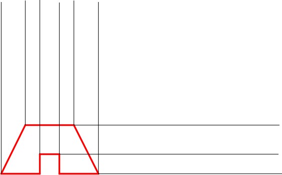
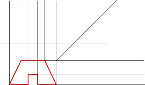
Using what you just learned, repeat the same thing by drawing horizontal lines from the three endpoints on the Front view. Guess at the length of the lines. (Figure Step 7)
Step 8
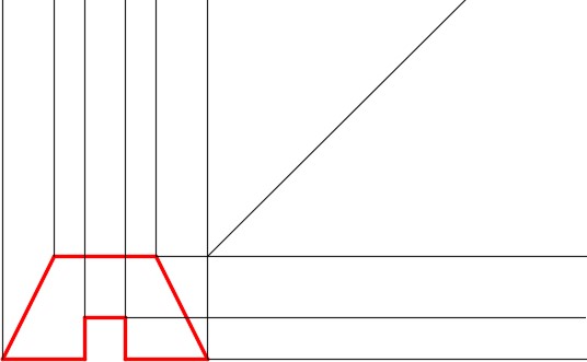
Draw a 45 degree line starting from the intersection of the construction line on the far right and the construction line on the top as shown in the figure. The line should be a least 200 units long. (Figure Step 8)
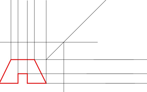
Step 9
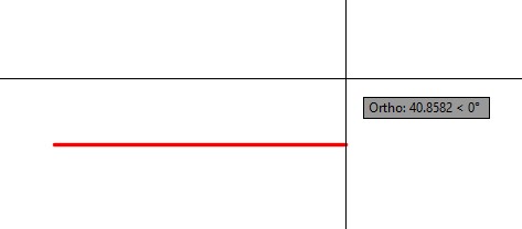
Using Ortho mode, draw a horizontal line as shown in the figure. The location and length of line is not important. Try to match the figure as close as you can by eye. (Figure Step 9)
Step 10
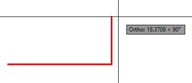
With Ortho mode enabled, draw a vertical line from the intersection of the inclined line and the line you drew in Step 9. (Figure Step 10)
Step 11
Using the OFFSET command, offset the line you drew in Step 9, 17.5 millimeters up. Repeat using 15 and 17.5 millimeters. (Figure step 11)
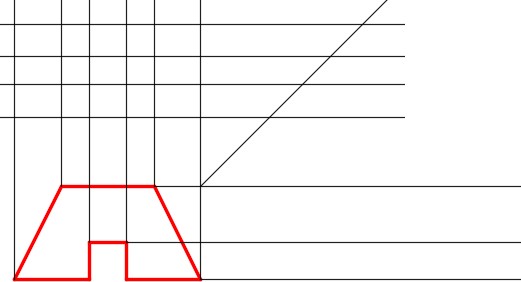
Step 12
With Ortho mode enabled, draw vertical lines from the intersection of the horizontal lines and the inclined line. Ensure that you start each line by snapping to the intersection of the lines. (Figure Step 12)
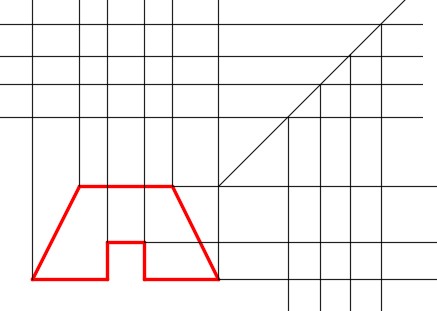
Step 13
Trim the lines in the top and Right Side views as shown in the figure. (Figure Step 13)
Step 14
In the Right Side view, offset the top line 10 millimeters down. With Ortho mode enabled, extend the line across the Front view. (Figure Step 14)
Step 15
From the point where the line you drew in Step 14 intersect the incline lines in the Front view, use Ortho mode and draw the lines vertical across the Top view. (Figure Step 15)
Step 16
Trim the lines in the Top and Right Side views to match the figure. (Figure Step 16)
Step 17
Change the object lines to layer: Object and the hidden lines to layer: Hidden. (Figure Step 17)
Step 18
Save and close the drawing.
Geometry Lesson: Drawing a Three Point Arc
Three Point Arc
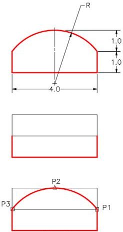
When the radius is not given for an arc, it can be drawn using with three known points on the arc. See Figure 28-3.
Step 1
Draw the construction lines to match the given dimensions.
Step 2
Enter the ARC command as shown below:
Command: ARC
Specify start point of arc or [Center]: (end) P1
Specify second point of arc or [Center/End]: (mid) P2
Specify end point of arc: (end) P3
Command:
Key Principles
Key Principles in Module 28
- If set, the grid always fills the rectangle or square shape defined by the limits of the drawing.
- The grid display and the snap density do not have to be set to the same size.
- The grid display is toggled with F7.
- Snap mode is toggled with F9.
- When Ortho mode is enabled, coordinate input can be shortcut when drawing lines. You only have to enter the distance along the direction of current axis from the lastpoint.
Lab Exercise 28-1
Time allowed: 45 minutes.
| Drawing Name | Template | Units |
|---|---|---|
| AutoCAD 2D Lab 28-1 | 2D Layout English | Inches |
Step 1
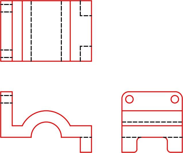
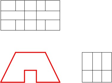
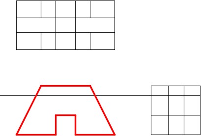
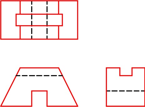
Using the figure, draw a multiview drawing of the object. Draw the Top, Front, and Right Side views. (Figure Step 1)
Step 2
Space the views 2 inches apart. (Figure Step 2)
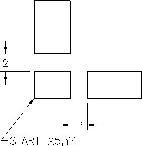
Location and Layout of Views
Step 3
Draw all construction lines on layer: Construction, the object lines on layer: Object, and the hidden lines on layer: Hidden.
Step 4
Check your drawing with the key.
Step 5
Save and close the drawing.
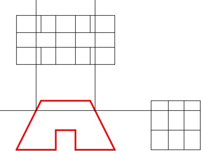
Hint 1
Draw the arc in the Front view using the User Tip at the start of this module. (Figure Hint 1)
Lab Exercise 28-2
Time allowed: 45 minutes.
| Drawing Name | Template | Units |
|---|---|---|
| AutoCAD 2D Lab 28-2 | 2D Layout English | Inches |
Step 1
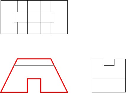
Using the figure, draw a multiview drawing of the object. Draw the Top, Front and Right Side views. (Figure Step 1),
Step 2
Space the views 2 inches apart. (Figure Step 2)
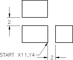
Location and Layout of Views
Step 3
Draw all construction lines on layer: Construction, the object lines on layer: Object, and the hidden lines on layer: Hidden.
Step 4
Check your drawing with the key.
Hint 1