Part 5
Module 22: Mirroring and Rotating
Learning Outcomes
When you have completed this module, you will be able to:
- Describe how drawing objects are mirrored using mirror lines.
- Describe how drawing objects are rotated.
- Apply the MIRROR and the ROTATE commands to mirror and rotate objects.
- Apply the MIRRTEXT system variable.
- Describe motion paths and explain how to draw and use them with the ROTATE command.
Mirroring
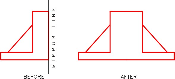
The MIRROR command is a very useful productivity tool. It is used to create a mirror image of an object saving you time that it takes to redraw the reverse image of the object. Before drawing any object, you should study it to see if it is symmetrical in any way and can be drawn faster by applying the MIRROR command.
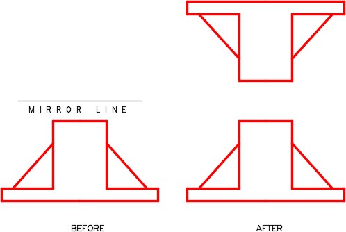
The objects to be mirrored are flipped around an axis. This axis is called a mirror line or a folding line. The mirror line is simply defined by two XY coordinates. The distance between the two XY coordinates is not important.
Mirroring
Mirroring
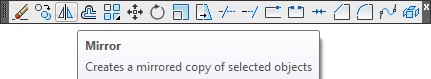
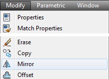
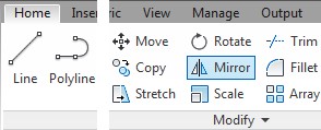
AutoCAD Command: MIRROR
The MIRROR command is used to mirror an object around a mirror line (folding line) to create a mirror image of the object.
Shortcut: MI
WORKALONG: Using the MIRROR Command – Part 1
Step 1
Start a new drawing using the template: 2D Layout English.
Step 2
Save and name the drawing: AutoCAD 2D Workalong 22-1.
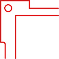
Step 3
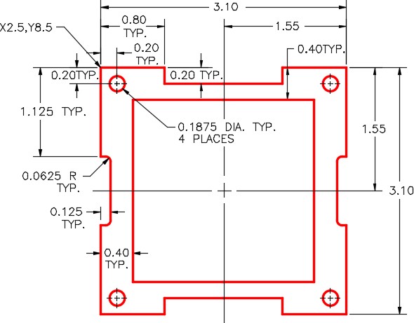
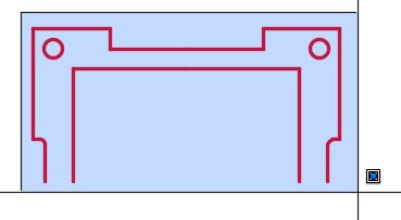
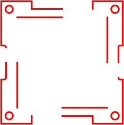
On layer: Object, draw one quarter of the object shown using the Figure Step 3A as a reference. (Figure Step 3A and 3B)
Step 4
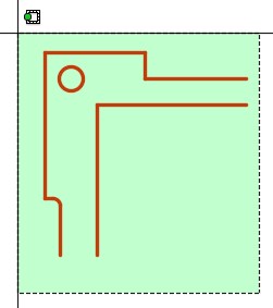
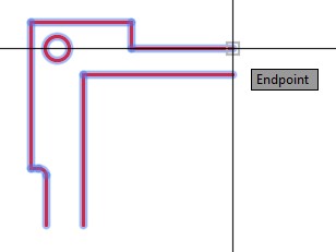
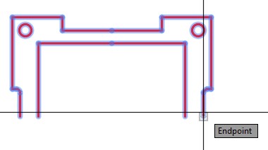
Enter the MIRROR command, as shown below, to mirror the object. (Figure Step 4A, 4B, 4C, and 4D)
Command: MIRROR
Select objects:
Specify opposite corner: 9 found
(Use a crossing window to select the objects to be mirrored.)
Select objects:
Specify first point of mirror line: (end)
Specify second point of mirror line: (end)
(Snap to the ends of the two lines to define the mirror line.)
Delete source objects? [Yes/No] <N>: N
(Enter No)
Command:
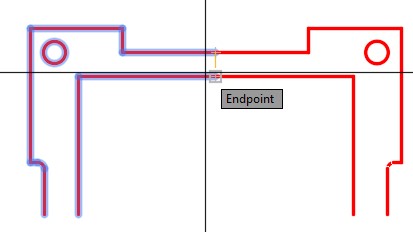
Mirroring Mirror Line Touching Object
Step 5
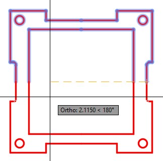
Enter the MIRROR command as shown below to mirror the object. (Figure Step 5A, 5B, 5C, and 5D)
Command: MIRROR
Select objects:
Specify opposite corner:
(Use a window to select all of the objects.)
Select objects:
Specify first point of mirror line: (end)
(Enable ortho mode.)
Specify second point of mirror line:
(With ortho mode enable, select any location in the -X direction.)
Delete source objects? [Yes/No] <N>: N
Command:

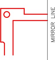
Mirror Line
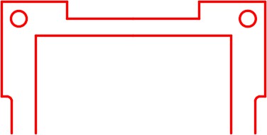
Step 6
Erase half of the lines that were mirrored as shown in the figure. See the Author’s Comments under Step 5. (Figure Step 6)
Step 7
Using the EXTEND command, extend the remaining lines to complete the object. (Figure Step 7)
Step 8
Save and close the drawing.
AutoCAD Command: MIRRTEXT
The MIRRTEXT system variable is used to control how the MIRROR command reflects text.
Shortcut: none
WORKALONG: Using the MIRROR Command – Part 2
Step 1
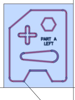
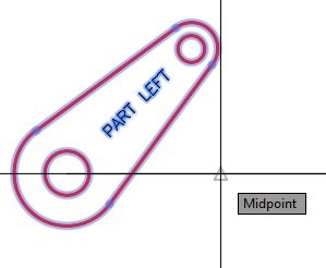
Open drawing: AutoCAD 2D Lab 14-1. (Figure Step 1)
Step 2
Using the SAVEAS command, save the drawing with the name: AutoCAD 2D Workalong 22-2 Left.
Step 3
Create a text style, with the font: romans, named: Module 22. Set it as the current text style.
Step 4
Create layer: Text with the color black/white and set it as the current layer.
Step 5
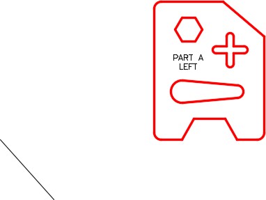
Enter the TEXT command. Using the justification of Middle and the Height of 0.2, insert two lines of text as shown in the figure. Locate it by eye. (Figure Step 5)
Step 6
Enter the MIRRTEXT system variable as shown below and set it to 0.
Command: MIRRTEXT
Enter new value for MIRRTEXT <1>: 0
Command:
Step 7
On layer: Construction, draw a line snapping the first end to the end of the lines. The second point can be anywhere on the drawing. (Figure Step 7).

Step 8
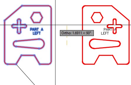
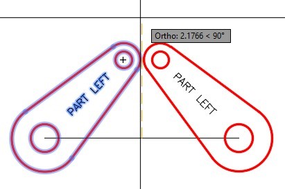
Enter the MIRROR command as shown below. (Figure Step 8A, 8B, and 8C)
Command: MIRROR
Select objects:
Specify opposite corner:
(Select the objects in a window)
Select objects:
Specify first point of mirror line:
(Select a point in space)
Specify second point of mirror line:
(With ortho enabled, select another point to draw a vertical line.)
Delete source objects? [Yes/No] <N>: Y
(Enter Yes)
Command:
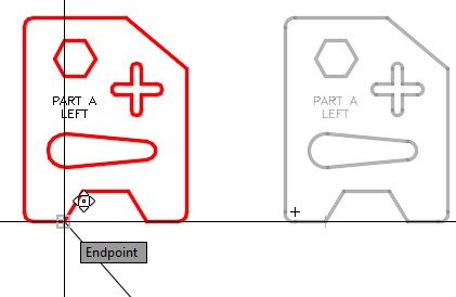
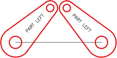
Step 9
Using the MOVE command, move the object by snapping to the end of the bottom lines for the base point the end of the construction line for the second point. (Figure Step 9A and 9B)
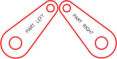
Step 10
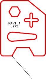
Edit the text to read PART A RIGHT. Freeze layer: Construction. (Figure Step 10)
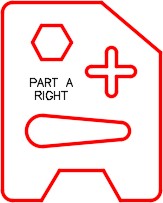
Step 11
Using the SAVEAS command, save the drawing with the name: AutoCAD 2D Workalong 22-2 Right.
Step 12
Save and close the drawing.
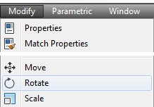
Rotating
The ROTATE command is a very useful productivity tool. It rotates selected objects around a base point the you select in the command. The base point is the only location on the rotated objects that is not changed after the rotation. The rotation can be defined by an angle or by a reference angle. By default, a positive angle rotates counterclockwise and a negative angle rotates clockwise.
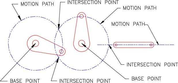
Motion Paths
A motion path is the path along a circle an object would follow if it was rotated around a base point or moved along a line. Study Figure 22-5.
Motion Paths
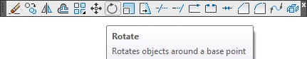
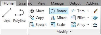
AutoCAD Command: ROTATE
The ROTATE command is used to rotate drawing objects around a base point.
Shortcut: RO
WORKALONG: Using the ROTATE Command
Step 1
Start a new drawing using the template: 2D Layout English.
Step 2
Save the drawing with the name: AutoCAD 2D Workalong 22-3.
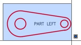
Step 3
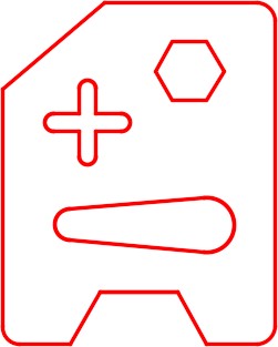
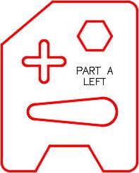
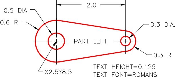
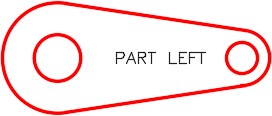
On layer: Rotation 1, draw the object shown in the figure. Draw the text on layer Text using the text style: 2D Modules. Locate it by eye. (Figure Step 3A and 3B)
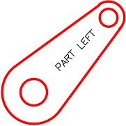
Step 4
Enter the ROTATE command, as shown below, to rotate the object 45 degrees counterclockwise. (Figure Step 4A, 4B, and 4C)
Command: ROTATE
Current positive angle in UCS: ANGDIR=counterclockwise ANGBASE=0
Select objects:
Specify opposite corner: 7 found
(Select all objects using a window.)
Select objects:
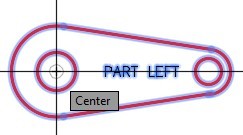
Specify base point: (cen)
(Snap to the center of the circle on the left for the base point.)
Specify rotation angle or [Copy/Reference] <0>: 45
(The positive rotation angle of 45 degrees is counterclockwise.)
Command:
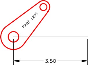
Step 5
On layer: Construction, draw a 3.5 inch line in the positive X direction. For the first point, snap to the center of the circle. (Figure Step 5)
Step 6
Using what you just learned in the last workalong, mirror the object to match the figure. Snap to the midpoint of the line for first mirror line location. With Ortho mode enable, select the second point vertical. (Figure Step 6A, 6B, and 6C)
Step 7
Freeze layer: Construction. Edit the text on the mirrored object to PART RIGHT. (Figure Step 7)
Step 8
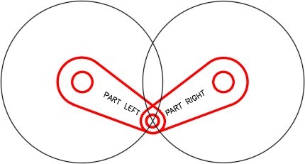
On layer: Motion Path 1, draw the motion path circle. Snap to the center of the lower left circle for the center point and the center of the upper left circle for the radius. (Figure Step 8)
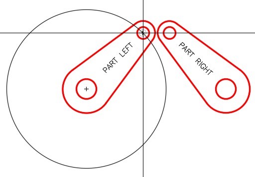
Step 9
Using what you just learned in Step 8, draw the motion path circle for the right arm. (Figure Step 9)
Step 10
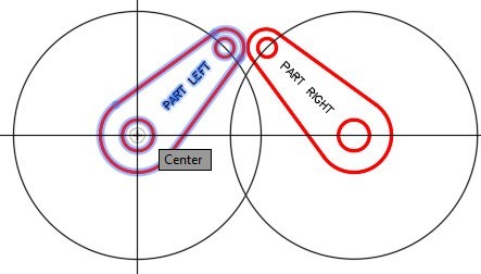
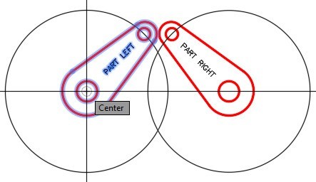
Enter the ROTATE command, as shown below, to rotate the left arm using the Reference option. (Figure Step 10A, 10B , 10C, 10D, 10E, and 10F)
Command: RO
Current positive angle in UCS: ANGDIR=counterclockwise ANGBASE=0
Select objects:
Specify opposite corner: 7 found
(Select the objects in a window.)
Select objects:
Specify base point: (cen)
(Selecting the center of the lower circle for base point.)
Specify rotation angle or [Copy/Reference] <90>: R
(Use a Reference.)
Specify the reference angle <0>: (cen)
(Specifying the center of the large circle (the base point) as the first point of the reference.)
Specify second point: (cen)
(Specifying the center of the small circle as the second point of the reference.)
Specify the new angle or [Points] <0>: (int)
(Specifying the new angle (the intersection of the motion paths). AutoCAD will find the rotation angle using the select location.)
Command:
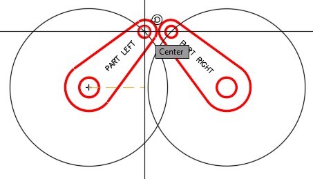
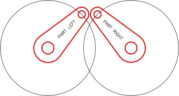
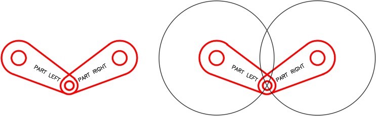
Step 11
Using what you just learned, rotate PART RIGHT to match PART LEFT. (Figure Step 11)
Step 12
Using the COPY command, copy only the arms beside the originals. It is not important where you locate the copy. (Figure Step 12)
Step 13
Change the layer of the copied arm to layer: Rotation 2. (Figure Step 13)
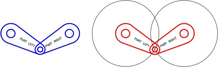
Step 14
Using the MOVE command, move the copied arms back to their original position on top of the original arms. Ensure that you locate them exactly on the originals by snapping the center of a circle to the center of matching circle. (Figure Step 14)
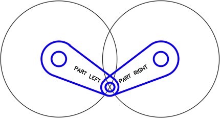
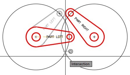
Step 15
Turn layer: Rotation 1 off. Using what you learned earlier in the workalong, rotated the arms on layer: Rotation 2 to match the figure. (Figure Step 15)
Step 16
Turn layer:
Rotation 1 on. Your drawing should match the figure. (Figure Step 16)
Step 17
Save and close the drawing.
Key Principles
Key Principles in Module 22
- When an object is mirrored, the object that is created in the mirror will retain all the properties of the object being mirrored.
- After mirroring, ensure that you correct any lines that appear full length but are actually two lines. You can do this by deleting one of the lines and extending the other one.
- The ROTATE command is a very useful productivity tool. It rotates objects around a base point selected in the command. The base point is the only location on the rotated object that is not changed after the rotation.
Lab Exercise 22-1
Time allowed: 50 minutes.
| Drawing Name | Template | Units |
|---|---|---|
| AutoCAD 2D Lab 22-1 | 2D Layout English | Inches |
Step 1
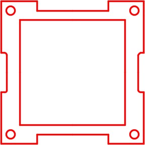
On layer: Object, draw the object shown in the figure. Start by drawing one quarter of the object, then mirror it once and then again to complete the drawing. (Figure Step 1A and 1B)
Step 2
Erase and extend all of the lines that were mirrored and are in two pieces.
Step 3
Set the insertion units and insert the key. Check the drawing for accuracy.
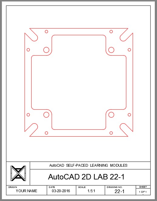
Completed Drawing
Step 4
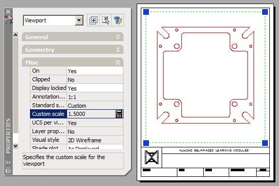
On layout: Module Layout A, create a viewport on layer: Viewport. Set the scale of the viewport to 1.5 and lock the display. (Figure Step 4)
Step 5
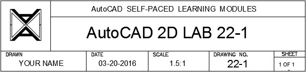
Complete the titleblock using the AutoCAD book Titleblock Standards shown in Module 20. (Figure Step 5)
Step 6
Turn layer: Viewport off. (Figure Step 6)
Step 7
Save and close the drawing.
Lab Exercise 22-2
Time allowed: 60 minutes.
| Drawing Name | Template | Units |
|---|---|---|
| AutoCAD 2D Lab 22-2 | 2D Layout Metric | Millimeters |
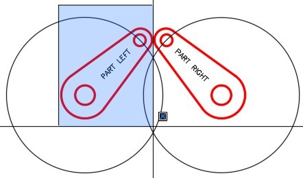
Step 1
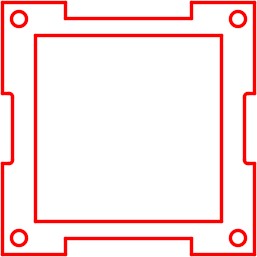
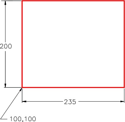
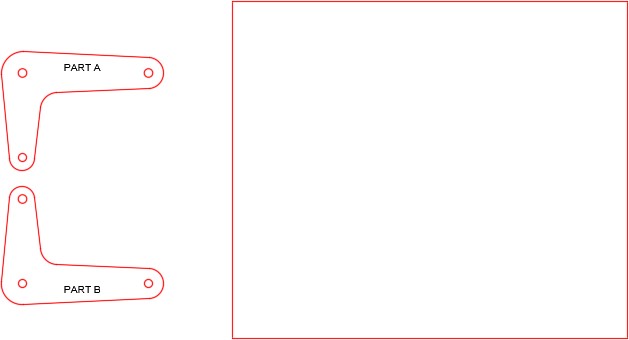
On layer: Object, draw the rectangle shown in the figure. (Figure Step 1)
Step 2
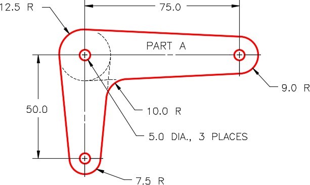
On layer: Rotation 1, draw the object shown in Figure step 2A using the dimensioned drawing as a reference. Draw it anywhere beside the rectangle. On layer: Text, insert the text PART A using the text style: 2D Modules. Locate the text by eye and select a text height to match the figure. (Figure Step 2A and 2B)
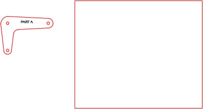
Step 3
Mirror the object PART A. The location is not important but ensure that the mirror line is horizontal. Edit the text to PART B. (Figure Step 3)
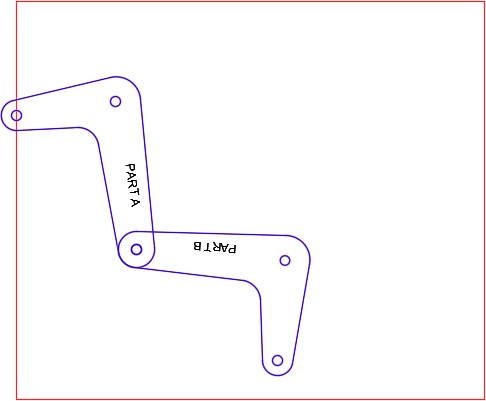
Step 4
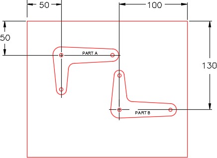
Using the dimensioned drawing shown in the figure as a reference, move PART A and PART B to locate them as shown in the figure. (Figure Step 4)
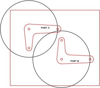
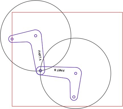
Step 5
On layer: Motion Path 1, draw the circles for the motion paths. Rotate the arms to locate them as shown in the figure. (Figure Step 5A and 5B)
Step 6
Turn layer: Motion Path 1 off. Copy both arms anywhere outside of the rectangle. Change the layer of the copied arms to layer: Rotation 2. (Figure Step 6)
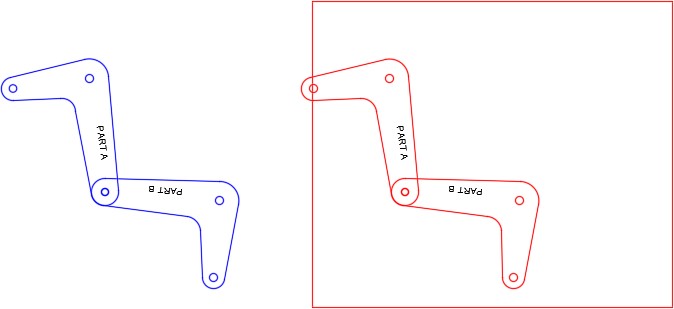
Step 7
Move the arms back to their exact original location. Turn layer: Rotation 1 off. (Figure Step 7)
Step 8
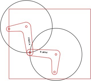
On layer: Motion Path 2, draw the motion path circle as shown in the figure. (Figure Step 8)
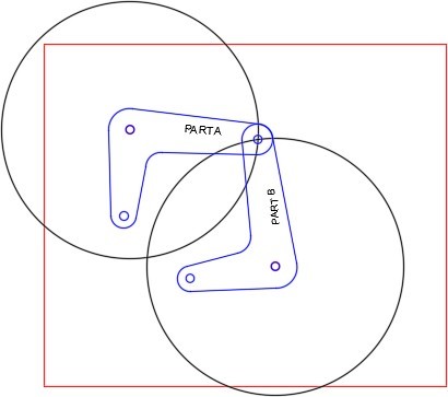
Step 9
Rotate the arms as shown in the figure. (Figure Step 9)
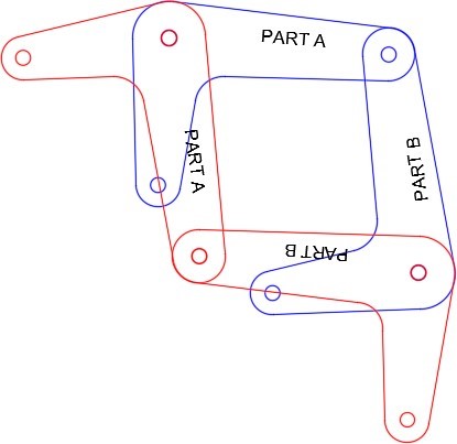
Step 10
Turn layers: Rotation 1, Rotation 2, and Text on and all other layers off. Your drawing should match the figure. (Figure Step 10)
Step 11
Set the insertion units and insert the key to check your drawing for accuracy.
Step 12
Save and close the drawing.
