Part 3
Module 15: Offsetting Objects
Learning Outcomes
When you have completed this module, you will be able to:
- Apply the OFFSET command to insert objects parallel to existing objects.
- Apply the ID command to establish temporary reference locations.
- Describe and apply the object snap mode Perpendicular.
Offsetting
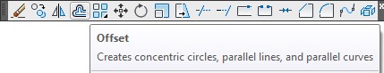
The OFFSET command allows you to create a drawing object parallel to an existing drawing object at a specified distance from the original object. OFFSET is a powerful command and if used when applicable, will change the way you construct objects and improve your drawing productivity. The drawing objects lines, circles, and arcs can be offset plus many others that you will be learning later in the book.
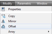
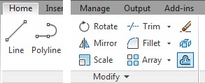
AutoCAD Command: OFFSET
The OFFSET command is used to create a drawing object parallel to an existing drawing object at a specified distance from the original object.
Shortcut: O
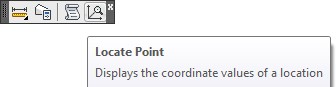
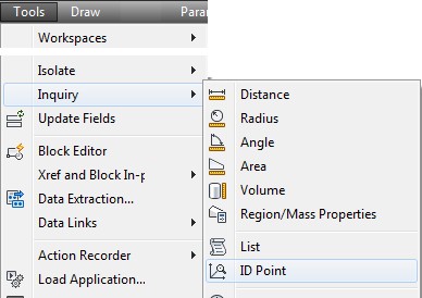
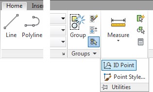
AutoCAD Command: ID
The ID command is used to return the coordinate location for a point in Model or Paper space.
Shortcut: none
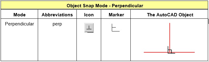
Object Snap Mode – Perpendicular
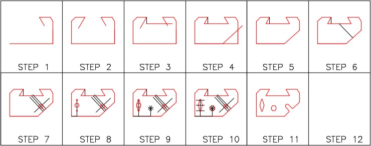
WORKALONG: Offsetting Objects
Step 1
Start a new drawing using the template: 2D English.
Step 2
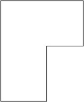
Save and name the drawing: AutoCAD 2D Workalong 15-1. (Figure Step 2)
Step 3
Create the layers: Object and Construction. Set layer: Construction as the current layer.
Step 4
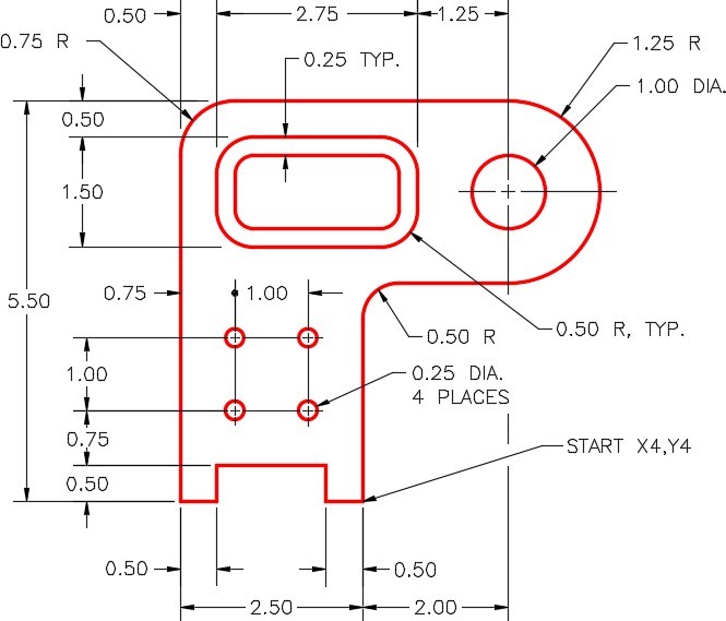
Enter the LINE command, as shown below, to create the outline of the object. (Figure Step 4)
Command: L
Specify first point: 4,4
Specify next point or [Undo]: @-2.5,0
Specify next point or [Undo]: @0,5.5
Specify next point or [Close/Undo]: @4.5,0
Specify next point or [Close/Undo]: @0,-2.5
Specify next point or [Close/Undo]: @-2,0
Specify next point or [Close/Undo]: C
Command:
Step 5
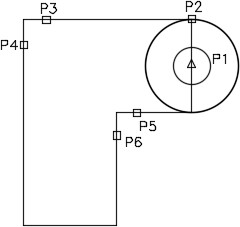
Enter the commands, as shown below, to draw the circles and fillets. (Figure Step 5A and 5B)
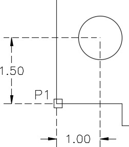
Command: C
Specify center point for circle or [3P/2P/Ttr (tan tan radius)]: (mid) P1
Specify radius of circle or [Diameter] <0.1000>: (end) P2
(When possible, it is always better to show AutoCAD a distance rather then entering it on the keyboard.)
Command: C
Specify center point for circle or [3P/2P/Ttr (tan tan radius)]: (mid) P1
Specify radius of circle or [Diameter] <0.7500>: D
Specify diameter of circle <1.5000>: 1
Command: F
Current settings: Mode = TRIM, Radius = 0.0000
Select first object or [Undo/Polyline/Radius/Trim/Multiple]: R
Specify fillet radius <0.0000>: 0.75
Select first object or [Undo/Polyline/Radius/Trim/Multiple]: P3
Select second object or shift-select to apply corner: P4
Command: F
Current settings: Mode = TRIM, Radius = 0.7500
Select first object or [Undo/Polyline/Radius/Trim/Multiple]: R
Specify fillet radius <0.7500>: 0.5
Select first object or [Undo/Polyline/Radius/Trim/Multiple]: P5
Select second object or shift-select to apply corner: P6
Command:
Step 6
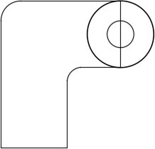
Use the TRIM command to trim the circle. (Figure Step 6)
Step 7
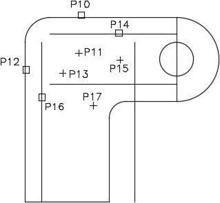
Enter the OFFSET commands, as shown below. (Figure Step 7)
Command: OFFSET
Current settings: Erase source=No Layer=Source OFFSETGAPTYPE=0
Specify offset distance or [Through/Erase/Layer] <Through>: 0.5
(Set the offset distance.)
Select object to offset or [Exit/Undo] <Exit>: P10
(Select the object to offset.)
Specify point on side to offset or [Exit/Multiple/Undo] <Exit>: P11
(Select which side of the object to offset it on.)
Select object to offset or [Exit/Undo] <Exit>: P12
Specify point on side to offset or [Exit/Multiple/Undo] <Exit>: P13
Select object to offset or [Exit/Undo] <Exit>:P14
Command: OFFSET
Current settings: Erase source=No Layer=Source OFFSETGAPTYPE=0
Specify offset distance or [Through/Erase/Layer] <0.5000>: 1.5
(Set the offset distance.)
Select object to offset or [Exit/Undo] <Exit>: P14
(Select the object to offset.)
Specify point on side to offset or [Exit/Multiple/Undo] <Exit>:P15
(Select which side of the object to offset it on.)
Select object to offset or [Exit/Undo] <Exit>:
Command: OFFSET
Current settings: Erase source=No Layer=Source OFFSETGAPTYPE=0
Specify offset distance or [Through/Erase/Layer] <1.5000>: 2.75
Select object to offset or [Exit/Undo] <Exit>: P16
Specify point on side to offset or [Exit/Multiple/Undo]
<Exit>:P17
Select object to offset or [Exit/Undo] <Exit>:
Command:
Step 8
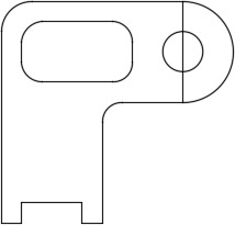
Using the FILLET command, insert a 0.5 radius fillet on all four corners. (Figure Step 8)
Step 9
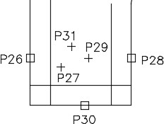
Enter the OFFSET command, as shown below. (Figure Step 9)
Command: O
Current settings: Erase source=No Layer=Source
OFFSETGAPTYPE=0
Specify offset distance or [Through/Erase/Layer] <Through>: 0.5
Select object to offset or [Exit/Undo] <Exit>: P26
Specify point on side to offset or [Exit/Multiple/Undo] <Exit>: P27
Select object to offset or [Exit/Undo] <Exit>: P28
Specify point on side to offset or [Exit/Multiple/Undo] <Exit>: P29
Select object to offset or [Exit/Undo] <Exit>: P30
Specify point on side to offset or [Exit/Multiple/Undo] <Exit>: P31
Select object to offset or [Exit/Undo] <Exit>:
Command:
Step 10
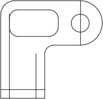
Using what you already learned, trim the lines to finish the bottom cutout. (Figure Step 10A and 10B)
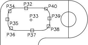
Step 11
Enter the OFFSET command, as shown below, to offset the inside feature. (Figure Step 11A and 11B)
Command: O
Current settings: Erase source=No Layer=Source OFFSETGAPTYPE=0
Specify offset distance or [Through/Erase/Layer] <Through>: 0.25
Select object to offset or [Exit/Undo] <Exit>: P32
Specify point on side to offset or [Exit/Multiple/Undo] <Exit>: P33
Select object to offset or [Exit/Undo] <Exit>: P34
Specify point on side to offset or [Exit/Multiple/Undo] <Exit>: P33
Select object to offset or [Exit/Undo] <Exit>: P35
Specify point on side to offset or [Exit/Multiple/Undo] <Exit>: P33
Select object to offset or [Exit/Undo] <Exit>: P36
Specify point on side to offset or [Exit/Multiple/Undo] <Exit>: P33
Select object to offset or [Exit/Undo] <Exit>: P37
Specify point on side to offset or [Exit/Multiple/Undo] <Exit>: P33
Select object to offset or [Exit/Undo] <Exit>: P38
Specify point on side to offset or [Exit/Multiple/Undo] <Exit>: P33
Select object to offset or [Exit/Undo] <Exit>: P39
Specify point on side to offset or [Exit/Multiple/Undo] <Exit>: P33
Select object to offset or [Exit/Undo] <Exit>: P40
Specify point on side to offset or [Exit/Multiple/Undo] <Exit>: P33
Select object to offset or [Exit/Undo] <Exit>:
Command:
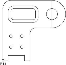
Step 12
Use the ID command to establish a lastpoint. Enter the CIRCLE command immediately following to insert the four circles using the lastpoint as a reference. (Figure Step 12)
Command: ID
Specify point: (end) P41
X = 1.5000
Y = 4.000
Z = 0.0000
(The ID command establishes a known reference point or an @ or lastpoint.)
Command: C
CIRCLE Specify center point for circle or [3P/2P/Ttr (tan tan radius)]: @0.75,1.25
(Now the @ can be used to measure the center of the circle from the end of the line selected in the ID command.)
Specify radius of circle or [Diameter]: D
Specify diameter of circle: 0.25
Command: C
CIRCLE Specify center point for circle or [3P/2P/Ttr (tan tan radius)]: @1,0
Specify radius of circle or [Diameter] <0.1250>: (Accept the default.)
Command: C
CIRCLE Specify center point for circle or [3P/2P/Ttr (tan tan radius)]: @0,1
Specify radius of circle or [Diameter] <0.1250>: (Accept the default.)
Command: C
CIRCLE Specify center point for circle or [3P/2P/Ttr (tan tan radius)]: @-1,0
Specify radius of circle or [Diameter] <0.1250>: (Accept the default.)
Command:
Step 13
Change the layer of the objects that you want to reside on layer: Object.
Step 14
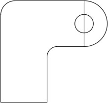
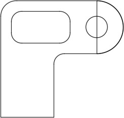
Freeze layer: Construction and your drawing should appear as shown in the figure. (Figure Step 14)
Step 15
Save and close the drawing.
WORKALONG: Drawing Construction Techniques
Step 1
Start a new drawing using the template: 2D English.
Step 2
Save and name the drawing: AutoCAD 2D Workalong 15-2. (Figure Step 2)
Step 3
Create the layers: Object and Construction. Set layer: Construction as the current layer.
Step 4
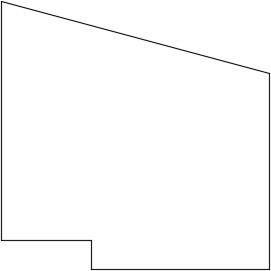
Using Figure Step 2 as an reference, draw lines to construct the perimeter of the object. (Figure Step 4)
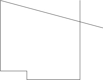
Step 5
Using what you already learned, trim the lines to complete the outline. (Figure Step 5)
Step 6
Enter the ID command, as shown below, to establish a lastpoint. Draw the circle using the reference point you established with the ID command. (Figure Step 6)
Command: ID
pecify point: (end) P1
X = 2.0000
Y = 5.5000
Z = 0.0000
(The lastpoint or the @ being established.)
Command: C
Specify center point for circle or [3P/2P/Ttr (tan tan radius)]: @1,1.5
(The center of the circle is now located using the reference point established in the ID command above. These commands must be entered back to back.)
Specify radius of circle or [Diameter] <2.6770>: D
Specify diameter of circle <5.3539>: 1
Command:
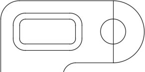
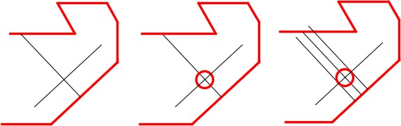
Step 7
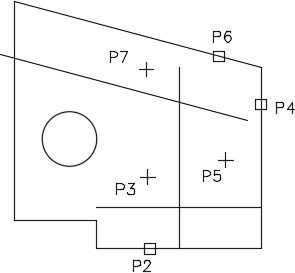
Enter the OFFSET command, as shown below, to insert the inside offsets. (Figure Step 7)
Command: O
(Shortcut for the OFFSET command)
Current settings: Erase source=No Layer=Source OFFSETGAPTYPE=0
Specify offset distance or [Through/Erase/Layer] <0.00>: 0.75
(Setting the offset distance.)
Select object to offset or [Exit/Undo] <Exit>: P2
Specify point on side to offset or [Exit/Multiple/Undo] <Exit>: P3
(First the object is selected (P2) and then the side of the object (P3) to place the offset. The location for P3 can be anywhere as long as it is above the line to be offset.)
Select object to offset or [Exit/Undo] <Exit>:
(With what you already learned, finish the other two offsets as shown in Figure Step 7.)
Command:
Step 8
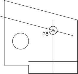
Enter the CIRCLE command, as shown below, to insert a circle by snapping its center to the intersection of the offset lines. (Figure Step 8)
Command: C
Specify center point for circle or [3P/2P/Ttr (tan tan radius)]: (int) P8
(Snap to locate the center of the circle at the intersection of the two offset lines.)
Specify radius of circle or [Diameter] <0.5000>: .25
Command:
Step 9
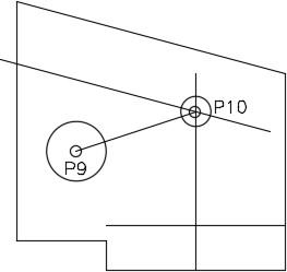
Draw a line between the centers of the circles. (Figure Step 9)
Command: L
Specify first point: (cen) P9
Specify next point or [Undo]: (cen) P10
(Draw a construction line by snapping to center point of the circles.)
Specify next point or [Undo]:
Command:
Step 10
Extend the construction line to the circle`s circumference. (Figure Step 10A and 10B)
Command: EX
Current settings: Projection=UCS, Edge=Extend
Select boundary edges …
Select objects or <select all>: P11 1 found
Select objects:
(Press enter or space.)
Select object to extend or shift-select to trim or
[Fence/Crossing/Project/Edge/Undo]: P12
Select object to extend or shift-select to trim or [Fence/Crossing/Project/Edge/Undo]:
Command:
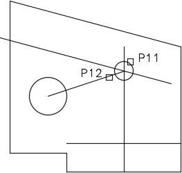
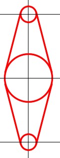
Step 11
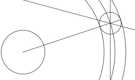
Draw a circle snapping to the center of the large circle for its center location and snapping to the intersection of the construction line and the lower circumference of the small circle for the radius. (Figure Step 11)
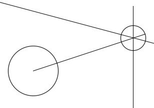
Step 12
Using the same principle that you learned in Step 11, insert the other two circles. Ensure that you snap one circle to the center of the small circle and the other to the intersection of the tangent line and circle circumference. (Figure Step 12A and 12B)
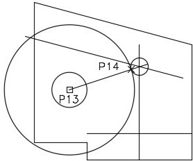
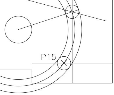
Step 13
Draw a circle locating its center at the intersection of the large circle’s centerline and the horizontal construction line. (Figure Step 13)
Command: C
Specify center point for circle or [3P/2P/Ttr (tan tan radius)]: (int) P15
Specify radius of circle or [Diameter]: .25
Command:
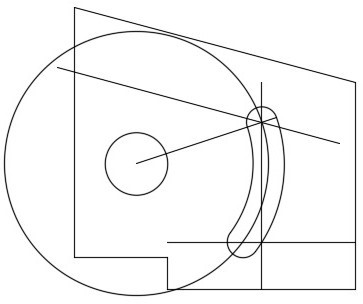
Step 14
Using what you already learned, trim the circles to complete the slot. (Figure Step 14)
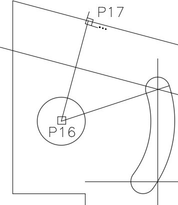
Step 15
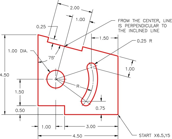
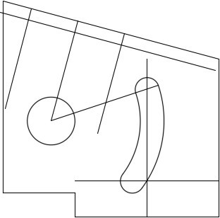
Enter the LINE command, as shown below, to draw a line from the center of the larger circle and snapping perpendicular to the inclined line. (Figure Step 15)
Command: L
Specify first point: (cen) P16
Specify next point or [Undo]: perp to P17
(It is much faster to type in the osnap mode perp then setting it in Autosnap.)
Specify next point or [Undo]:
Command:
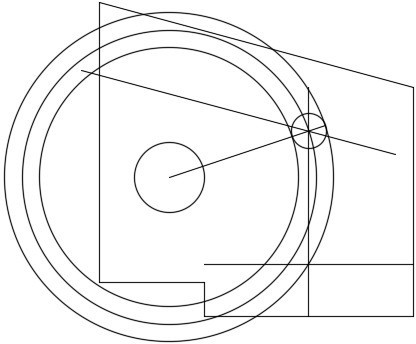
Step 16
Using what you already learned, offset the lines to create top feature. (Figure Step 16)
Step 17
Trim the lines to complete the top cutout. (Figure Step 17)
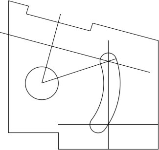
Step 18
Change the layer of the objects to layer: Object. Freeze layer: Construction to complete the drawing. (Figure Step 18)

Step 19
Save and close the drawing.
Key Principles
Key Principles in Module 15
- The OFFSET command is a very useful command. When used at the right times, it will improve your drawing speed and change the way you construct objects in AutoCAD.
- When a drawing object is offset, the newly constructed offset drawing object will reside on the same layer as the original object, regardless of the current layer.
- The ID command can be used to established a known reference point or an @. The reference point can then be used, in the next command, to measure from.
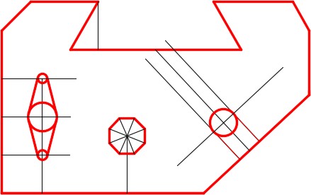
Lab Exercise 15-1
Time allowed: 40 minutes.
| Drawing Name | Template | Units |
|---|---|---|
| AutoCAD 2D Lab 15-1 | 2D English | Inches |
| Layer Name | Objects on Layer | Color |
|---|---|---|
| Construction | Construction objects | 253 |
| Object | All objects | Red |
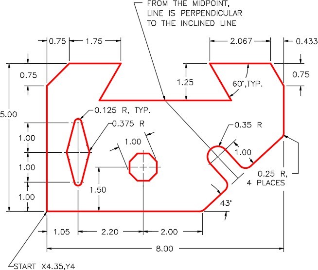
Step 1
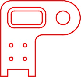
Draw the object shown in the figure using the layering scheme. (Figure Step 1A and 1B)
Step 2
Set the insertion units and check the drawing’s accuracy.
Step 3
Turn layer: Key off and freeze layer: Construction.
Step 4
Save and close the drawing.
Hint 1
Draw the line perpendicular to inclined line and then offset the inclined line. Draw a circle with its center located at the intersection of the lines. Offset the perpendicular line using the radius of the circle as the distance and trim. (Figure Hint 1)
Hint 2
Insert offset lines as construction lines to locate the centers of the three circles. Then draw the lines tangent to the circles. (Figure Hint 2)
Hint 3
The figure shows the construction lines. (Figure Hint 3)
Lab Exercise 15-2
Time allowed: 60 minutes.
| Drawing Name | Template | Units |
|---|---|---|
| AutoCAD 2D Lab 15-2 | 2D Metric | Millimeters |
| Layer Name | Objects on Layer | Color |
|---|---|---|
| Construction | Construction objects | 253 |
| Object | All objects | Red |
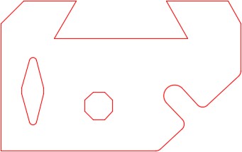
Step 1
Draw the object shown in the figure using the layering scheme. (Figure Step 1A and 1B)
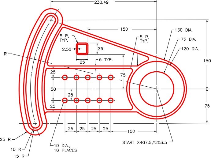
Step 2
Set the insertion units and check the drawing’s accuracy.
Step 3
Turn layer Key off and freeze layer Construction.
Step 4
Save and close the drawing.
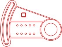
Completed Drawing
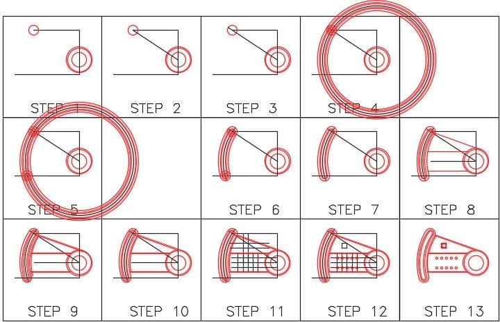
Hint 1
See the figure and the following seven steps:
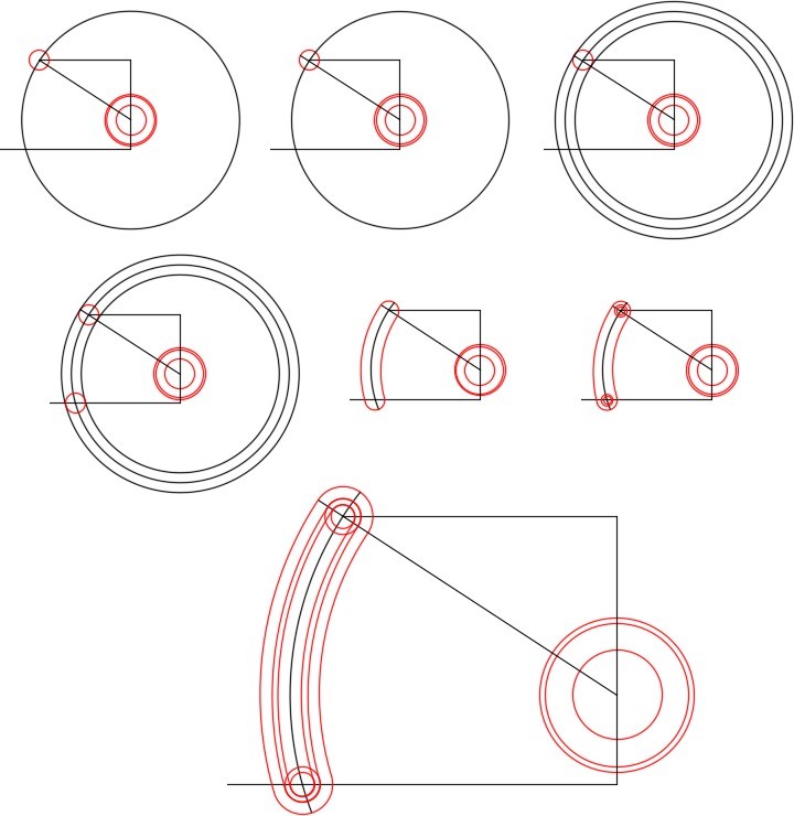
Step 1
Draw a construction line from the center of the bottom circle to the center of the upper circle.
Step 2
Extend the line to the upper circumference of the circle.
Step 3
Draw circles using the intersection of the tangent line and circle to show AutoCAD the radius.
Step 4
Draw the bottom circle at the intersection of the construction circle and line.
Step 5
Trim the circles.
Step 6
Draw the inner circles.
Step 7
Offset the arcs and trim to complete. (Figure Hint 1)
Lab Exercise 15-3
Time allowed: 40 minutes.
| Drawing Name | Template | Units |
|---|---|---|
| AutoCAD 2D Lab 15-3 | 2D English | Inches |
| Layer Name | Objects on Layer | Color |
|---|---|---|
| Construction | Construction objects | 253 |
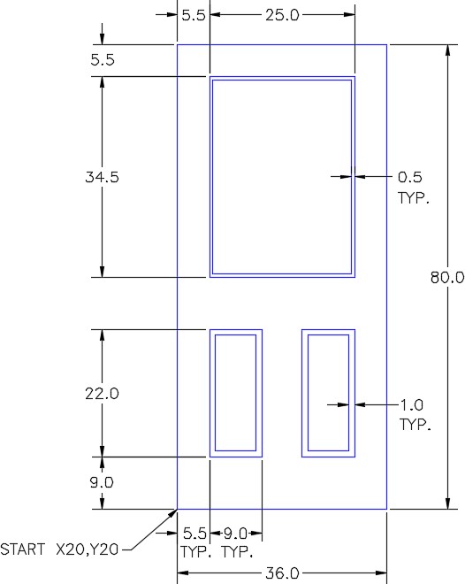
| Door | All lines | Blue |
Step 1
Set the LIMITS as follows:
The lower left corner to: 0.0,0.0
The upper right corner to: 100,150
Step 2
Enter the ZOOM Extents command.
Step 3
Draw the object shown in the figures using the layering scheme. (Figure Step 3A, 3B, and 3C)
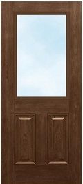
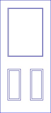
Completed Drawing
Step 4
Set the insertion units and check your drawing with the key. Turn layer: Key off and freeze layer: Construction.
Step 5
Save and close the drawing.
