Part 6
Module 30: Regular Polygons
Learning Outcomes
When you have completed this module, you will be able to:
- Describe a regular polygon and the methods used to construct them.
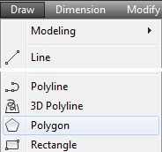
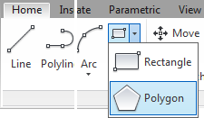
- Apply the POLYGON command to create regular polygons using three methods.
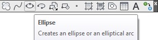
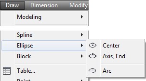
- Apply the ELLIPSE command to create ellipses.
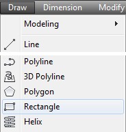
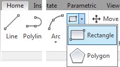
- Apply the RECTANGLE command to create rectangles.
- Apply the AREA command to measure areas and perimeters.
- Describe how to work with and add and subtract angles with degrees minutes and seconds.
Drawing Regular Polygons
A regular polygon is a closed polyline having between 3 and 1,024 equal-length sides. Regular polygons can be drawn using the POLYGON command. Using the POLYGON command to create polygons is a fast and simple way to draw squares, equilateral triangles, hexagons, octagons, and any other regular polygon. See Module 14.
A Regular Polygon
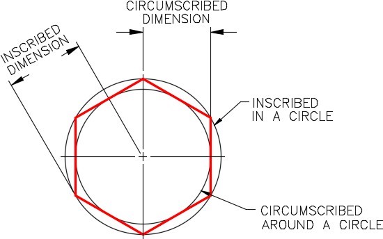
A polygon drawn using the POLYGON command constructs a closed pline. Polygons can be constructed using the inscribed, circumscribed, or the edge method. See Figure 30-1 and 30-2. Since the polygon drawn by the POLYGON command is a polyline, it is one object in AutoCAD. It can be exploded into individual lines using the EXPLODE command.
Even though a square can be constructed using the POLYGON command, they are easier to draw using the RECTANGLE command.
Drawing a Regular Polygon – Edge Method
AutoCAD Command: POLYGON
The POLYGON command is used to create closed polylines to form regular polygons that have between 3 to 1024 sides.
Shortcut: POL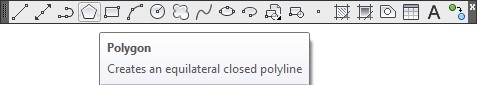
AutoCAD Command: RECTANGLE
The RECTANGLE command is used to construct a 4 sided polygon using a closed polyline in the shape of a rectangle or a square.
Shortcut: REC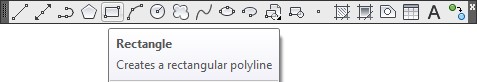
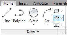
AutoCAD Command: ELLIPSE
The ELLIPSE command is used to construct ellipses or elliptical arcs.
Shortcut: EL
Geometry Lesson: Ellipse
An ellipse is determined by two axes that define its length and width. The longer axis is called the major axis, and the shorter one is the minor axis. The center of the ellipse is located at the intersection of the axes. The rotation angle of the ellipse determines length of the minor axis compared to the length of the major axis. See Figure 30-3.
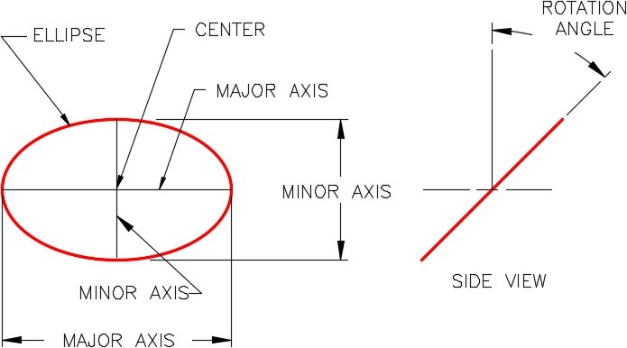
An Ellipse
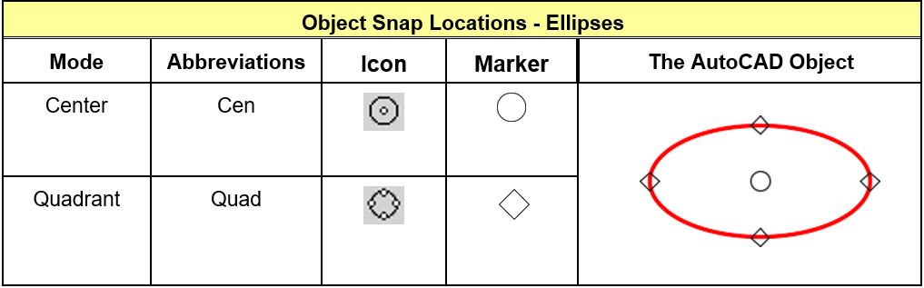
Object Snap Location for Ellipses
WORKALONG: Using the POLYGON, RECTANGLE and ELLIPSE Commands
Step 1
Start a new drawing using the template: 2D Layout English.
Step 2
Save and name the drawing: AutoCAD 2D Workalong 30-1.
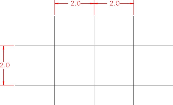
Step 3
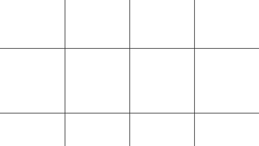
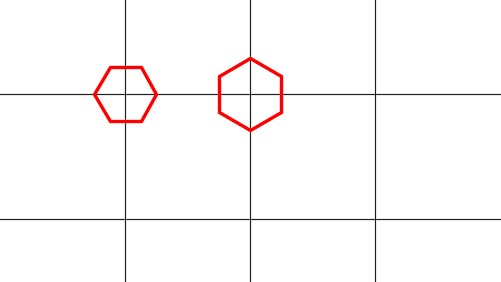
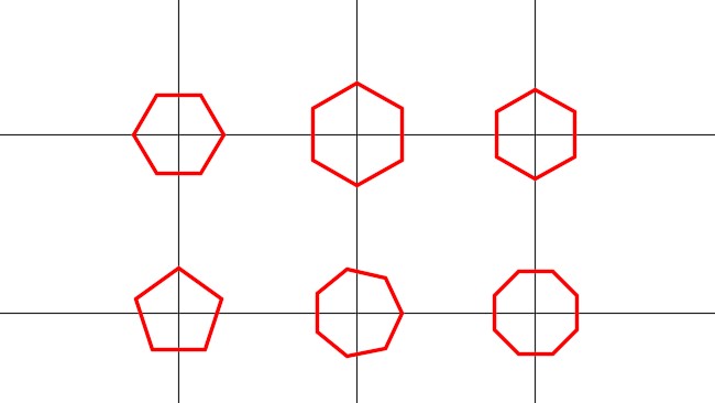
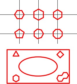
On layer: Construction, draw two horizontal and 3 vertical lines as shown in the dimensioned drawing. Where you start the drawing is not important. (Figure Step 3A and 3B)
Step 4
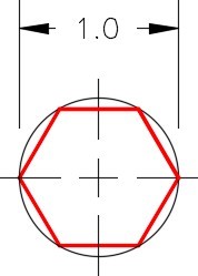
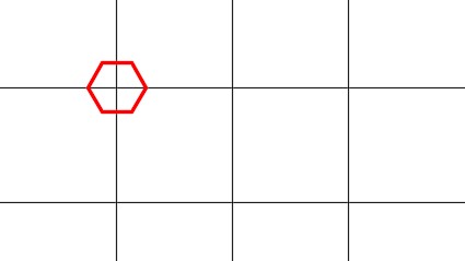
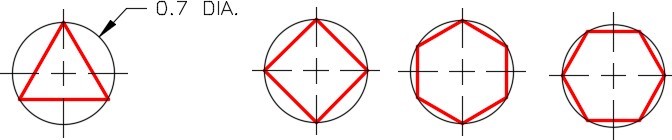
Set layer: Object as the current layer. Enter the POLYGON command, as shown below, to draw a hexagon with its center at the intersection of the top and left line. (Figure Step 4A and 4B)
Step 5
Enter the POLYGON command, as shown below, to draw the hexagon with its center at the intersection of the top and the center line. (Figure Step 5A and 5B)
Command: POL
Enter number of sides <8>: 6
(Enter the number of sides of the polygon.)
Specify center of polygon or [Edge]: (int)
(Snap to the intersection of the two lines.)
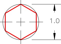
Enter an option [Inscribed in circle/Circumscribed about circle] <C>: I
(This is an inscribed polygon since it is dimensioned to a corner.)
Specify radius of circle: @0.5<0
(Radius of the inscribed circle.)
Command:
Step 5
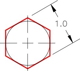
Enter the POLYGON command, as shown below, to draw the hexagon with its center at the intersection of the top and the center line. (Figure Step 5A and 5B)
Command: POL
Enter number of sides <8>: 6
(Enter the number of sides of the polygon.)
Specify center of polygon or [Edge]: (int)
(Snap to the intersection of the two lines.)
Enter an option [Inscribed in circle/Circumscribed about circle] <I>: C
(This is a circumscribed polygon.)
Specify radius of circle: @0.5<0
(Radius of the circumscribed circle.)
Command:
Step 6
Enter the POLYGON command, as shown below, to draw a hexagon with its center at the intersection of the top and the right line. (Figure Step 6A and 6B)
Command: POL
Enter number of sides <8>: 6
Specify center of polygon or [Edge]: (int)
Enter an option [Inscribed in circle/Circumscribed about circle] <I>: I
Specify radius of circle: @0.5<90
(Radius and location of the corner of the polygon.)
Command:
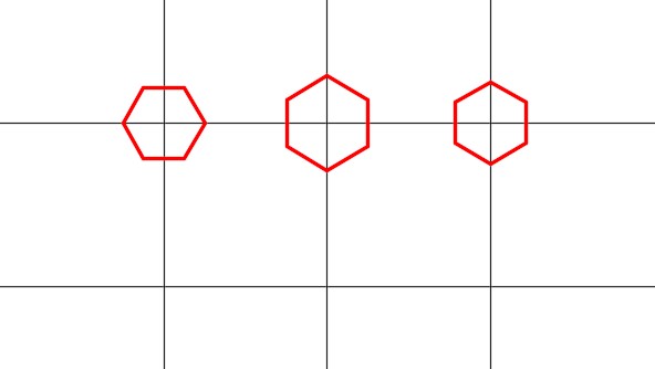
Step 7
Using what you learned in Steps 4 to 6, draw the three regular polygons and locate them as shown in the figure. (Figure Step 7A and 7B)
Step 8
On layer: Object, enter the RECTANGLE command, as shown below, to draw the rectangle. (Figure Step 8)
Command: RECTANGLE
Specify first corner point or [Chamfer/Elevation/Fillet/Thickness/Width]: 1,2.5
Specify other corner point or [Area/Dimensions/Rotation]: 7.5,6
Command:
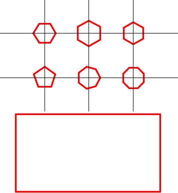
Step 9
On layer: Construction, draw diagonal lines by snapping from corner to corner of the rectangle. (Figure Step 9)
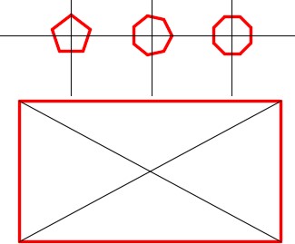
Step 10
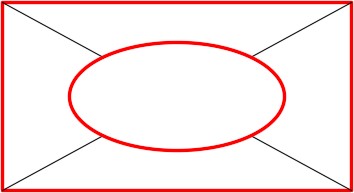
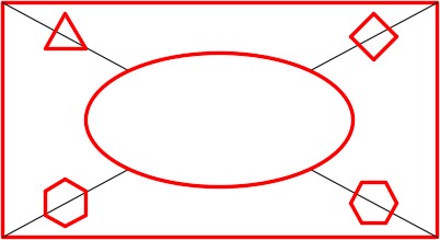
On layer: Object, using the figure as a reference, enter the ELLIPSE command, as shown below, to draw the ellipse. (Figure Step 10A and 10B)
Command: ELLIPSE
Specify axis endpoint of ellipse or [Arc/Center]: C
Specify center of ellipse: (int)
(Snap to the intersection of the two diagonal lines to located the center of the ellipse.)
Specify endpoint of axis: @2,0
Specify distance to other axis or [Rotation]: @0,1
Command:

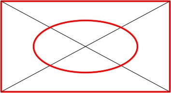
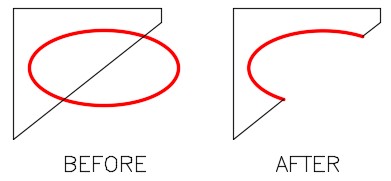
Step 11
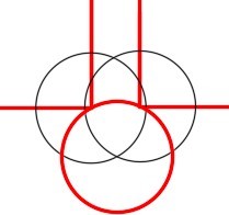
Trim the construction lines inside the ellipse. (Figure step 11)
Step 12
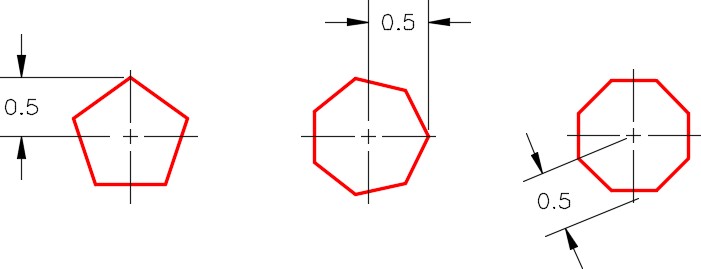
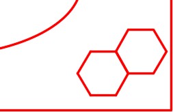
Using what you learned earlier in this workalong, on layer: Object, draw the four polygons shown in the figure. Locate the centers of the polygons at the midpoint of each construction line. (Figure Step 12A and 12B)
Step 13
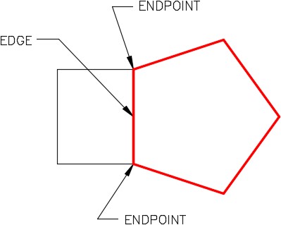
Turn layer: Construction off. Enter the POLYGON command, as shown below, to draw a hexagon using the Edge method. (Figure 13A and 13B)
Command: POL
POLYGON Enter number of sides <8>: 6
Specify center of polygon or [Edge]: E
Specify first endpoint of edge: (end) P1
Specify second endpoint of edge: (end) P2
Command:
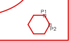
Step 14
Explode both polygons and delete the lines they share. (Figure Step 14)
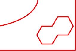
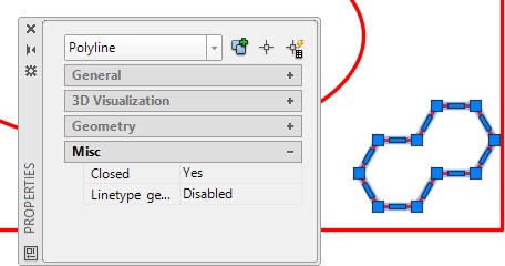
Step 15
Using what you learned in Module 29, use the PEDIT command to create a closed polyline. Using the Properties window, confirm that the polygon you just created is closed. (Figure Step 15)
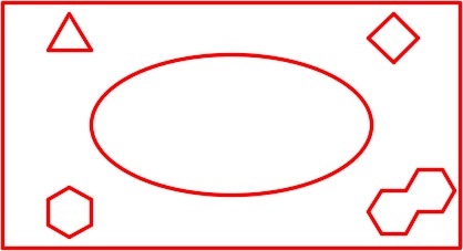
Step 16
The bottom section of your drawing should appear as shown in the figure. (Figure Step 16)
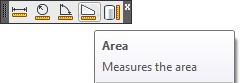
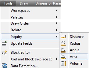
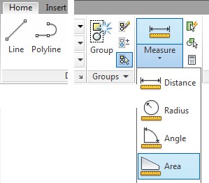
AutoCAD Command: AREA
The AREA command is used to find the area or perimeter of a series of coordinates, a closed polyline, circle or ellipse.
Shortcut: none
WORKALONG: Using the AREA Command
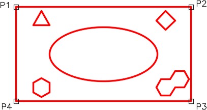
Step 1
Open the drawing: AutoCAD 2D Workalong 30-1. (Figure Step 1)
Step 2
Enter the AREA command, as shown below, to measure the area of the rectangle using the Corner Point method. (Figure Step2)
Command: AREA
Specify first corner point or [Object/Add/Subtract]: (end) P1
Specify next corner point or press ENTER for total: (end) P2
Specify next corner point or press ENTER for total: (end) P3
Specify next corner point or press ENTER for total: (end) P4
Specify next corner point or press ENTER for total: (press Enter)
(You do not have to snap back to the start point. The AREA command will go back to the first point and calculate the area and perimeter.)
Area = 22.7500, Perimeter = 20.0000
Command:
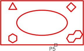
Step 3
Enter the AREA command, as shown below, to measure the area and perimeter of the rectangle using the Object method. (Figure Step 3)
Command: AREA
Specify first corner point or [Object/Add/Subtract]: O
(Using the Object method.)
Select objects: P5
(Select the object. It must be a closed polygon, a circle or an ellipse.)
Area = 22.7500, Perimeter = 20.0000
(This answer will match the results found in Step 2)
Command:
Step 4
Enter the AREA command, as shown below, to measure the area of the rectangle subtracting objects from the overall area. (Figure Step 4)
Command: AREA
Specify first corner point or [Object/Add/Subtract]: A
(Specifying you want to be in Add mode.)
Specify first corner point or [Object/Subtract]: O
(ADD mode) Select objects: P6
(Add in the rectangle area.)
Area = 22.7500, Perimeter = 20.0000
Total area = 22.7500
(ADD mode) Select objects:
(Press enter to end the Add mode)
Specify first corner point or [Object/Subtract]: S
(Beginning the Subtract mode.)
Specify first corner point or [Object/Add]: O
(SUBTRACT mode) Select objects: P7
Area = 0.1591, Perimeter = 1.8187
Total area = 22.5909
(SUBTRACT mode) Select objects: P8
Area = 0.3183, Perimeter = 2.1000
Total area = 22.2726
(SUBTRACT mode) Select objects: P9
Area = 6.2832, Perimeter = 9.6884
Total area = 15.9894
(SUBTRACT mode) Select objects: P10
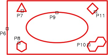
Area = 0.6365, Perimeter = 3.5000
Total area = 15.3529
(SUBTRACT mode) Select objects: P11
Area = 0.2450, Perimeter = 1.9799
Total area = 15.1079
(SUBTRACT mode) Select objects:
(Press Enter to end the Subtract mode.)
Total area = 15.1079
(The area of the overall object minus the 5 inner objects is 15.1079 square inches.)
Command:
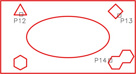
Step 5
Enter the AREA command, as shown below, to measure and add the areas of three individual objects. (Figure Step 5)
Command: AREA
Specify first corner point or [Object/Add/Subtract]: A
(Enter the Add mode.)
Specify first corner point or [Object/Subtract]: O
(ADD mode) Select objects: P12
Area = 0.1591, Perimeter = 1.8187
Total area = 0.1591
(ADD mode) Select objects: P13
Area = 0.2450, Perimeter = 1.9799
Total area = 0.4041
(ADD mode) Select objects: P14
Area = 0.6365, Perimeter = 3.5000
Total area = 1.0407
(The total area of the three objects combined is 1.0407 square inches.)
Command:
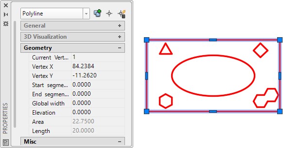
Step 6
Open the Properties window and select the large rectangle. The area and the perimeter (length) will display. (Figure Step 6)
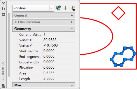
Step 7
Unselect the rectangle and select the object in the bottom right. The area and the perimeter (length) will display. (Figure Step 7)
Geometry Lesson: Degrees Minutes and Seconds
Since a full degree is not always precise enough to measure an angle, you must be able to work to a more precise measurement. Degrees are broken down to smaller and more precise units of minutes and seconds.
1 degree is divided into 60 minutes and 1 minute is divided into 60 seconds:
1 degree = 60 minutes
1 minute = 60 seconds
Therefore, 1 degree = 3600 seconds.
Degrees are written 1E, minutes are written 01′ and seconds 01″.
Combined: 1<01’01”.
Here are some examples of adding and subtracting angles with degree minutes and seconds. Study them and then solve problems A to F below.
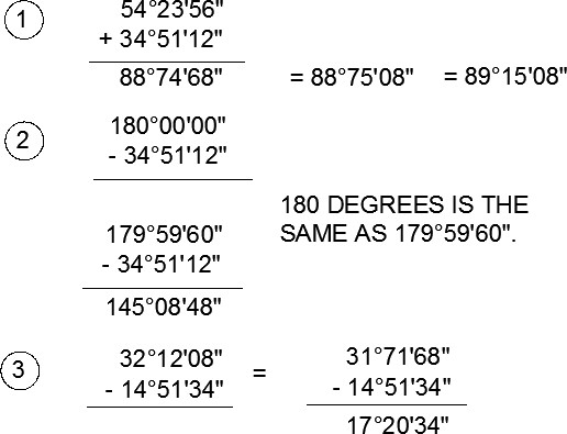
Adding and Subtracting Degrees Minutes Seconds
Solve the following problems of adding and subtracting degrees, minutes and seconds. The answers are shown below.
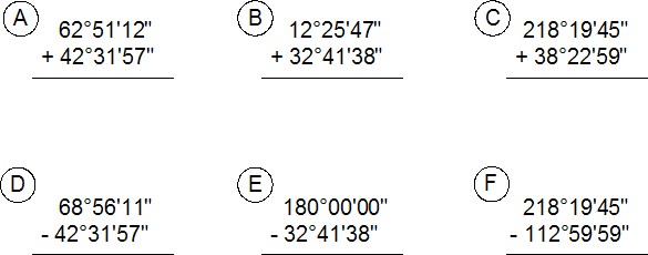
Answers to Adding and Subtracting Degrees Minutes Seconds:
A 105E23’09”
B 45E07’25”
C 256E42’44”
D 26E24’14”
E 147E18’22”
F 105E19’46”
Working in Degrees Minutes and Seconds
Up to this point in the book, all of the angles have been entering using degrees and decimals of a degree. The values of degrees can also be entered using degree/minutes/seconds.
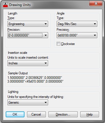
The Drawing Units dialogue box must be set to report angular units and precision in degree/minutes/seconds. The Angle Type must be set to Deg/Min/Sec and the Precision set to the value that you want it reported. See Figure 30-5.
Since there is no degree symbol on the keyboard, enter the letter ‘ d ‘ after the number when entering degrees in response to an AutoCAD prompt.
For example: 34d
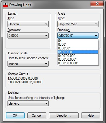
Setting the Angle Type and Precision
To specify the number of minutes, enter a ‘ (single quote) after the number and to enter seconds, enter a ” (double quote) after the number. See Figure 30-6.
For example: 34d56’32” Command: LINE
Specify first point: 2,2
Specify next point or [Undo]: @2<34d56’32”
Specify next point or [Undo]:
Command:
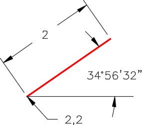
An Angle Using Deg/Min/Sec
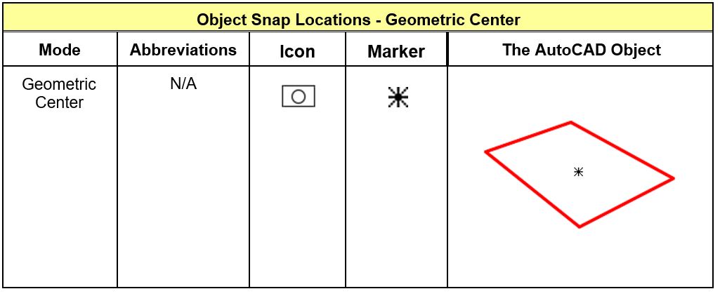
Object Snap Location for Geometric Center
Note: Geometric Center osnap mode snaps to the centroid of any closed polyline.
Key Principles
Key Principles in Module 30
- A regular polygon is a closed polyline having between 3 and 1,024 equal-length sides and is drawn using the POLYGON command.
- The EXPLODE command converts a polygon made from an open or closed polyline back into its individual line objects. When exploded, polylines will lose their assigned widths.
Lab Exercise 30-1
Time allowed: 60 minutes.
| Drawing Name | Template | Units |
|---|---|---|
| AutoCAD 2D Lab 30-1 | 2D Layout English | Inches |
Step 1
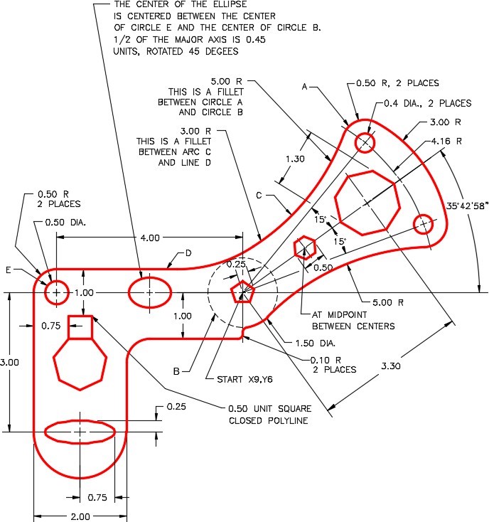
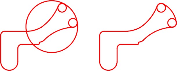
On layer: Object, draw the object shown in the figures. (Figure Step 1A and 1B)
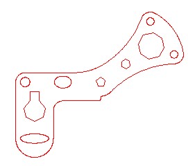
Completed Drawing
Step 2
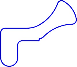
On layer: Boundary, using the PEDIT command, create a closed polygon of the outside outline of the object. (Figure Step 2)
Step 3
To the precision of 4 decimal places, find the area and perimeter of the closed polygon created in Step 2.
A Area = ___________________
B Perimeter = ___________________
Step 4
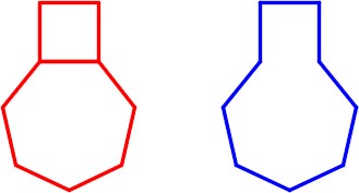
Change the square and the heptagon to appear as shown in the figure. On layer Boundary, using the BOUNDARY command, create a closed polygon of the new shape. (Figure Step 4)
Step 5
To the precision of 6 decimal places, find the area and perimeter of the closed polygon created in Step 4.
A Area = ___________________
B Perimeter = ___________________
Hint 1
To draw the 3 radius tangent arc on the top right side of the object, you must draw a tangent circle and then trim it. The FILLET command cannot be used as it will draw the fillet on the inside. Use the CIRCLE command and the TTR option to insert the tangent circle and then trim it. (Figure Hint 1)
Lab Exercise 30-2
Time allowed: 60 minutes.
| Drawing Name | Template | Units |
|---|---|---|
| AutoCAD 2D Lab 30-2 | 2D Layout English | Feet |
Step 1
Start a new drawing using the template shown above. (Figure Step 1)
All Dimensions in are Feet
Step 2
Using the UNITS command, set the Length type to Engineering, the Angle type to Deg/Min/Sec and Units to scale inserted content: to Inches, as shown in the figure. (Figure Step 2)
Step 3
On layer: Lot Lines, draw the first line of the model, as shown below: (Figure Step 3A and 3B)
Command: LINE
Specify first point: 200.0′,1200.0‘
(Make sure that all numbers are followed by the ‘ character.)
Specify next point or [Undo]: @1200.0′,0′
Specify next point or [Undo]:
Command: ZOOM
Specify corner of window, enter a scale factor (nX or nXP), or
[All/Center/Dynamic/Extents/Previous/Scale/Window/Object] <real time>: E
Regenerating model.
Command:

Step 4
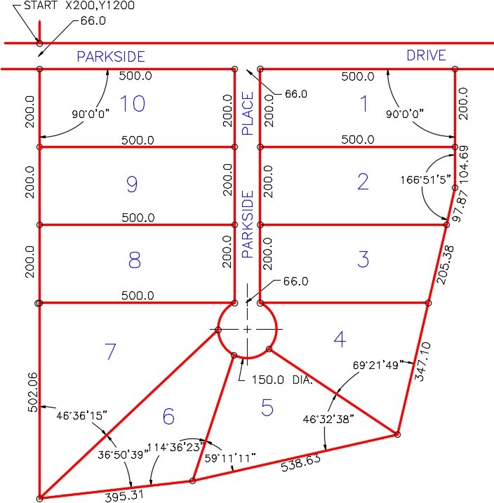
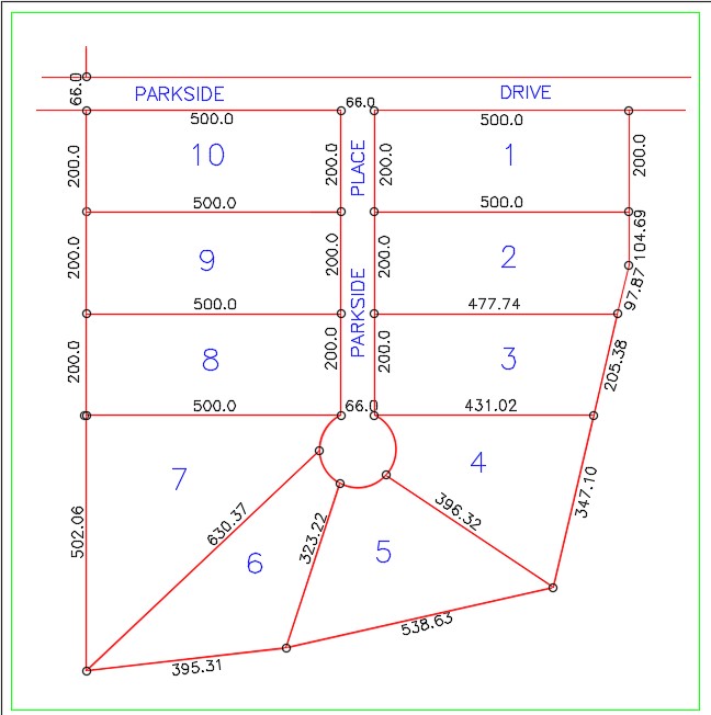
On layer: Lot Lines, complete the model using the dimensioned drawing shown in Step 1. The input must be is feet and decimals of a foot. (Figure Step 4)
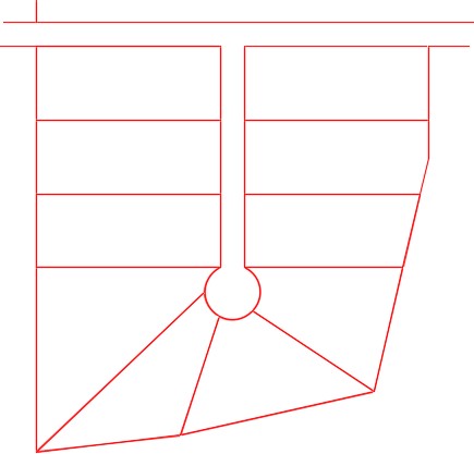
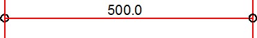
AUTHOR’S COMMENTS MINI-SURVEY PLAN LESSON: The length of the lots, on survey maps, are dimensioned by placing the length dimension parallel and along the lot line it is referring to. The length is measured from corner of the lot to corner of the lot. In Figure 30-8, the distance is 500.0 feet. The pin, small circles at the ends, have nothing to do with the dimensions. They only show where the surveyor has placed a metal pin in the ground when the survey was completed. When you draw the map, draw all the lines and then insert 10 feet diameter circles snapping their centers at the ends of the lines.
Step 5
On layer: Lot Pins, draw circles, with 10 foot diameters, to indicate the location of the survey pins. Hint: Draw one circle and copy it to the other locations. (Figure Step 5)
Step 6
With INSUNITS set to Inches, insert the key to check your model for accuracy.
Step 7
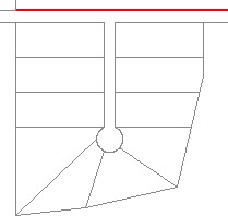
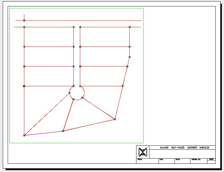
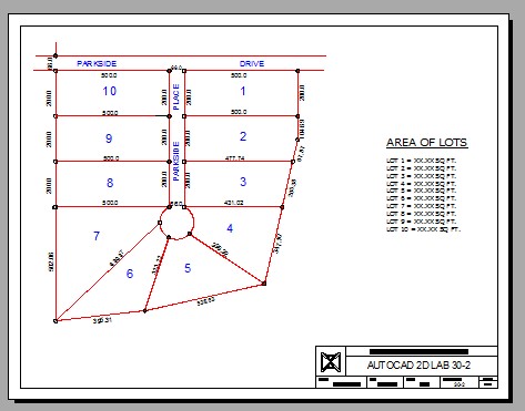
Enable layout: Module Layout C. On layer: Viewport, create a viewport as shown in the figure. Set the scale to 1:1200 or 0.000833 and lock the display. (Figure Step 7)
Step 8
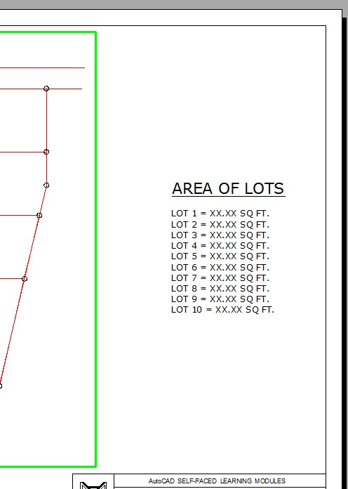
Using the AREA command, find the area of each of the 10 lots. On layer: Text, in paper space, insert the text as shown in the figure. Edit the text with the applicable area. Fill in the titleblock. (Figure Step 8)
Step 9
In Paper space, on layer: Lot Dimensions, insert the dimensions of the lot lines as shown in the figure. On layer: Lot Labels, insert text of the street name and the lot numbers. Create your own text style, pick the font and select the text height. (Figure Step 9)
Step 10
Turn layer: Viewport off to complete the drawing. (Figure Step 10)
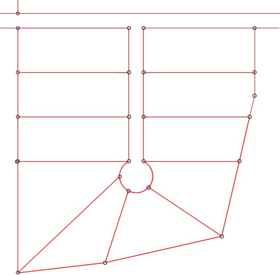
Hint 1
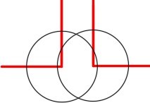
To draw the arc in the center, first draw two 150 foot diameter circles on layer: Construction. Use the ends of the lot lines as the center locations. Where the circles intersect is the center of the 150 foot diameter arc. Draw a circle and then trim it. (Figure Hint 1A and 1B).
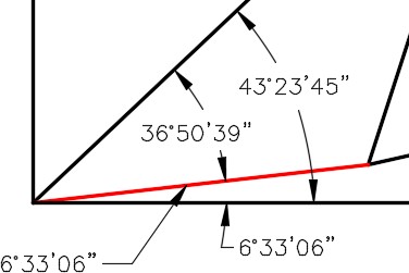
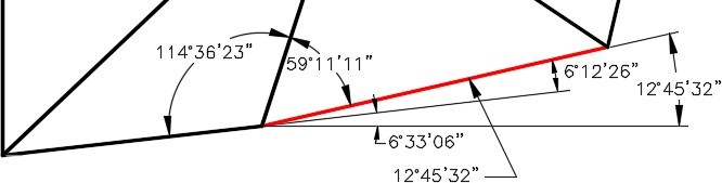
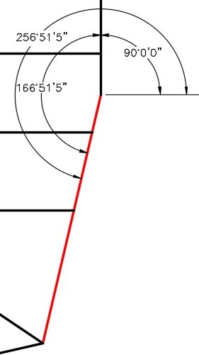
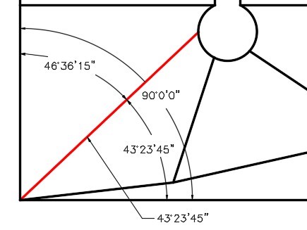
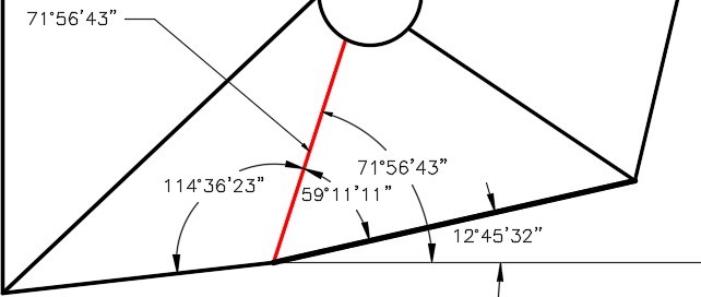
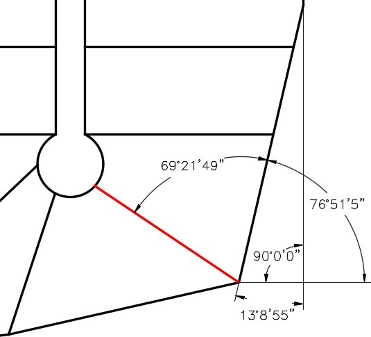
Hint 2
Figure Hint 2A to 2F will help you calculate the angles.