Part 5
Module 25: Text – Part 2
Learning Outcomes
When you have completed this module, you will be able to:
- Describe a mtext object and explain how to create, edit and explode mtext.
- Apply the MTEXT, QTEXT, and SPELL commands.
- Describe and compare shape and true type text fonts and their characteristics.
- Describe special text characters and the use of control codes.
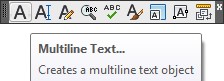
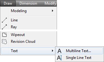
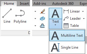
Multiline Text
Unlike single line text, that was taught Module 19, multiline text, also called mtext, is a text object that can contain one or more lines of text. AutoCAD contains an editor that inserts and edits mtext similar to a word processor. Mtext uses the current text style for its properties, just like single line text, but it allows the font color and appearance of the text, with the same style, to be changed. This cannot be done with single line text.
Mtext can be exploded using the EXPLODE command. When exploded, it is converted into single line text objects and loses all of its mtext properties except the color, height, and text style.
AutoCAD Command: MTEXT
The MTEXT command is used to insert one or more lines of multiline text objects. Each mtext is a single drawing object.
Shortcut: MT
WORKALONG: Using the MTEXT Command
Step 1
Start a new drawing using the template: 2D Layout English.
Step 2
Save and name the drawing: AutoCAD 2D Workalong 25-1.
Step 3
Create a new text style naming it: Module 25 and assign the font: romans.shx. Set Standard as the current text style.
Step 4
Enable layout: Module Layout A.
Step 5
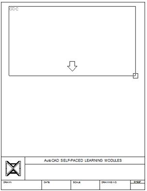
Set layer: Text as the current layer and while in paper space, enter the MTEXT command as shown below. (Figure Step 5)
Command: MTEXT
Current text style: “Standard” Text height: 0.2000
Specify first corner:
Specify opposite corner or [Height/Justify/Line spacing/Rotation/Style/Width]:
(Select two corners to form a window as shown in the figure. The size and location are not that important but try to match the figure the best you can.)
Step 6
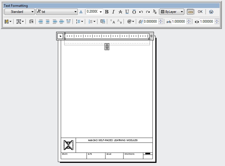
The MTEXT command will open the Text Formatting dialogue box. It works similar to a simple word processor. (Figure Step 6)
Step 7
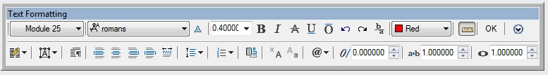
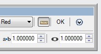
Set layer: Text as the current layer. Set the text style to: Module 25, the text height to 0.4 and the color to Red as shown in the figure. (Figure Step 7)
Step 8
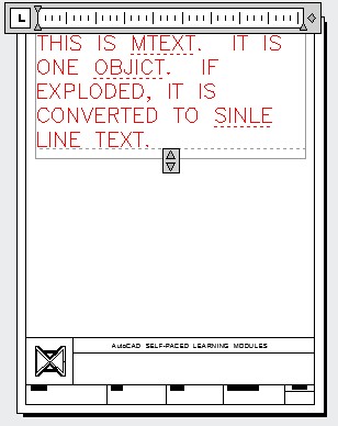
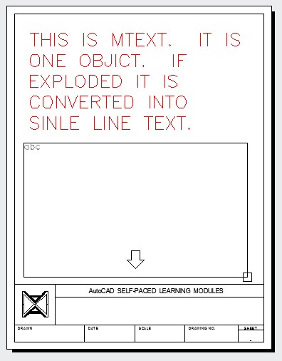
In the bounding box, enter the text shown below. Use uppercase letters. Do not press the Enter key at the end of the line, just keep typing. Do not correct the spelling errors in the text, type it as shown. (Figure Step 8)
THIS IS MTEXT. IT IS ONE OBJICT. IF EXPLODED, IT IS CONVERTED TO SINLE LINE TEXT.
Step 9
Click OK after you have entered all the text. (Figure step 9)
Step 10
Enter the MTEXT command as shown below. (Figure Step 10)
Command: MTEXT
Current text style: “Module 25” Text height: 0.4000
Specify first corner:
Specify opposite corner or [Height/Justify/Line spacing/Rotation/Style/Width]:
(Select two corners to form a window. The size and location are not that important but try to match the figure the best you can.)
Command:
Step 11
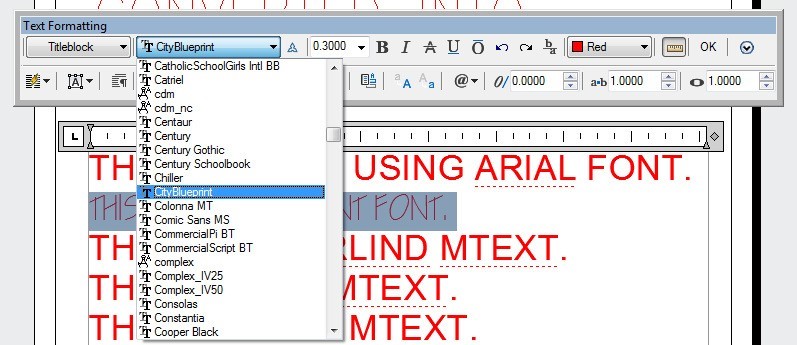
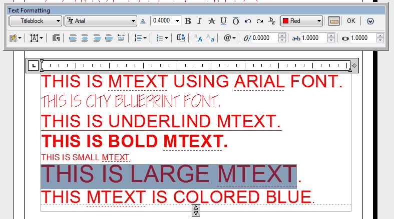
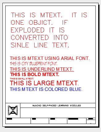
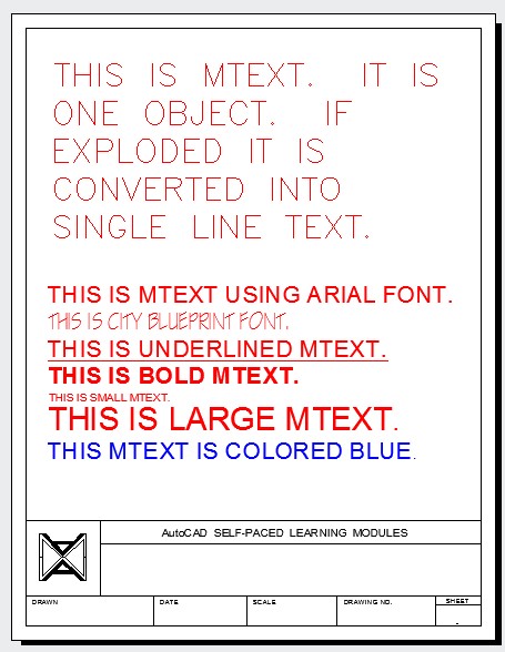
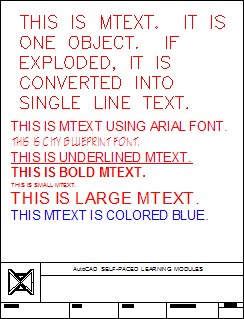
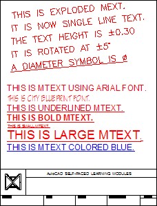
Set the text style to: Titleblock, font Arial and height to 0.3 as shown in the figure. In the bounding box, enter the text shown below. Enter it in upper case characters. At the end of each line press the Enter key. Do not correct the spelling errors in the text, type it as shown. (Figure Step 11A and 11B)
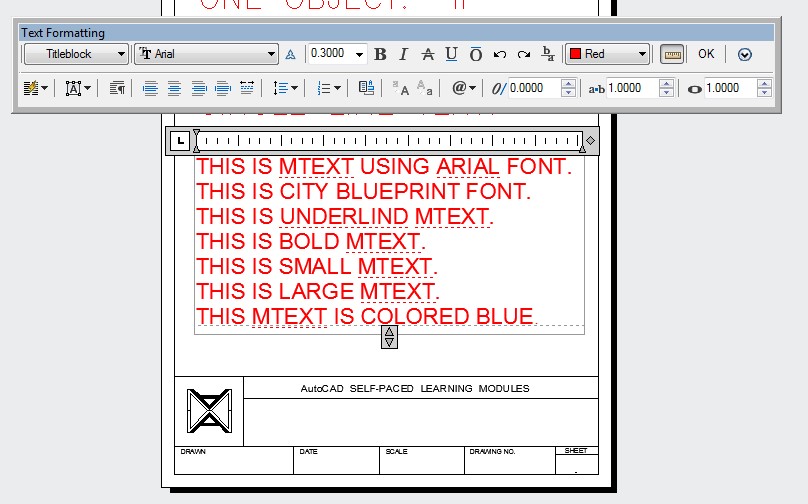
THIS IS MTEXT USING ARIAL FONT.
THIS IS CITY BLUEPRINT FONT.
THIS IS UNDERLIND MTEXT.
THIS IS BOLD MTEXT. THIS IS SMALL MTEXT.
THIS IS LARGE MTEXT.
THIS MTEXT IS COLORED BLUE.
Step 12
Block the second line of the text. While it is blocked, select the font: City Blueprint. (Figure Step 12)
Step 13
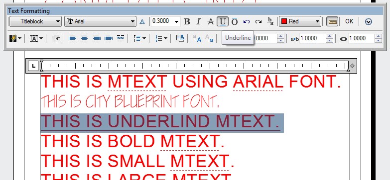
Block the third line. While it is blocked, click the Underline icon. (Figure Step 13)
Step 14
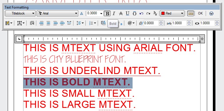
Block the forth line. While it is blocked, click the Bold icon. (Figure Step 14)
Step 15
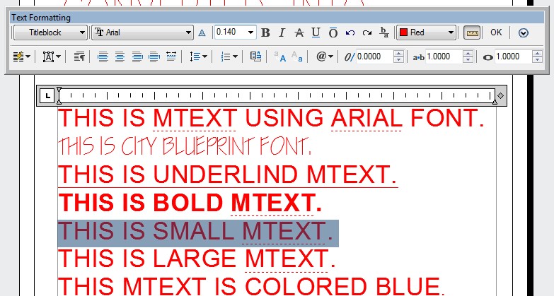
Block the fifth line. While it is blocked, set the text height to 0.14. (Figure Step 15)
Step 16
Block the sixth line. While it is blocked, set the text height to 0.40. (Figure Step 16)
Step 17
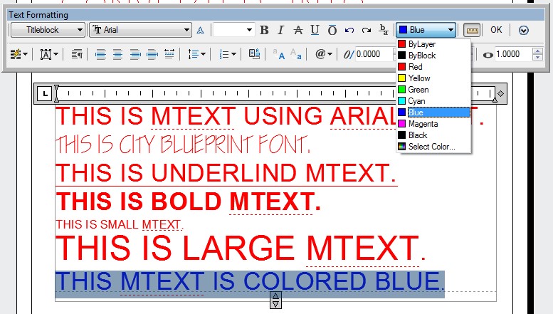
Block the seventh line. While it is blocked, set the color to Blue. (Figure Step 17)
Step 18
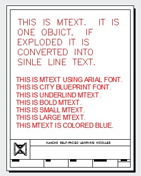
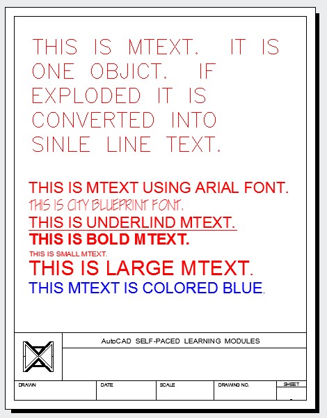
The completed drawing should appear as shown in the figure. (Figure Step 18)
Step 19
Save and close the drawing.
Editing Mtext
The DDEDIT command, taught in Module 19, is used to edit mtext. You can enter the DDEDIT command on the command line or enter it from one of the menus and then select the mtext to edit. A much faster method to edit mtext is to double click the mtext. When mtext is double- clicked, it will open the Text Formatting dialogue box and display the selected mtext.
AutoCAD Command: SPELL
The SPELL command is used to spell check selected text or all text in the current drawing.
Shortcut: SP
AutoCAD Command: QTEXT
The QTEXT command is used to change the display of all text objects on the drawing to rectangles that represent the location of the text.
Shortcut: none
Font Types
There are two basic font types available in AutoCAD. They are shape fonts and true type fonts.
Shape Font
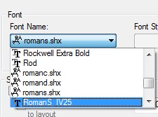
A shape font is a compiled font created using vector lines and arcs. The text characters in a shape font are made from lines and arcs, the same as drawings. They are created in a text file, saved as a shape file, and compiled before they can be used in a drawing. A shape file is saved with the extension .shp and after it is compiled, is given a .shx extension. See Figure 25-2.
True Type and Shape Fonts
True Type Fonts
A true type font is a raster font. The text characters in a raster font are created from dots or pixels. A true type font does not have a file extension assigned to the name.
A Shape Font Verses a True Type Font
The fonts available in the Text Style dialogue box are either shape fonts or true type fonts. Shape fonts have the extension .shx while true type fonts do not have an extension. That is how you can tell which font type is being used. See Figure 25-2.
The main differences between shape fonts and true type fonts are as follows:
- Shape fonts take much less space in an AutoCAD drawing’s data base then true type
- Drawings regenerate faster with shape fonts then they do with true type
- True type fonts can be assigned appearances like bolding and italicized while shape fonts cannot.
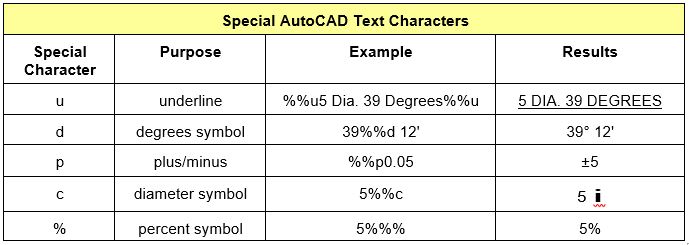
Special Text Characters
Not all characters or symbols that are required on drawings are available on a keyboard. These characters are called special characters, see Figure 25-3. To enter them as text, control codes must be used.
Control Codes
The control code used by AutoCAD is a pair of percent signs %%. Added before a special character, AutoCAD’s text commands will interpret it differently than normal text characters. Shape and true type fonts as well as single line and multiline text work differently with special characters. Therefore, you will have to experiment with the text type and font being used.
WORKALONG: Using the SPELL and QTEXT Commands plus Special Characters
Step 1
Open the drawing:
AutoCAD 2D Workalong 25-1. Enable layout: Module Layout A. (Figure Step 1)
Step 2
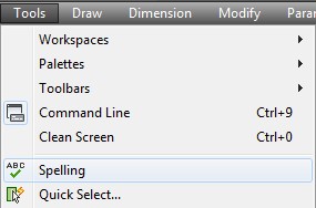
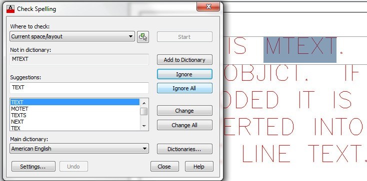
Enter the SPELL command. It will open the Check Spelling dialogue box. Pull down the Where to check: list and select Current space/layout. Press the Start button. (Figure Step 2)
Step 3
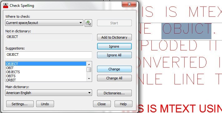
One by one, the dialogue box will display the words it finds that are not in the dictionary and may suggest a replacement. You have the choice to Ignore, Change or to Add the word to the dictionary. In this case, click the Ignore All box. It will ignore all mtext words in the layout. (Figure Step 3)
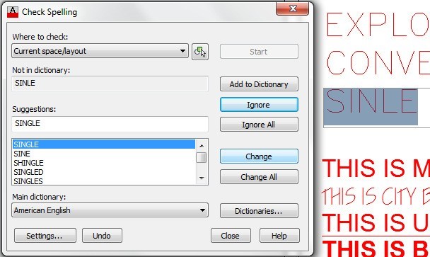
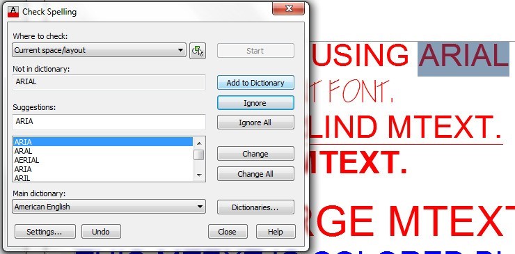
Step 4
This spell checker will find the next misspelled word. In this example, it is OBJICT. Click the Change box to correct the spelling to OBJECT. This spell checker will find the next misspelled word. In this example, it is SINLE. Carry on using the spell checker until it completes checking all words. When the spell checker finds ARIAL, click the Add to Dictionary box to add the word. (Figure step 4A. 4B, and 4C).
Step 5
Your drawing should now appear as shown in the figure with the spelling errors corrected. (Figure Step 5)
Step 6
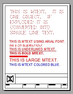
Enter the QTEXT command as shown below. (Figure Step 6)
Command: QTEXT
Enter mode [ON/OFF] <OFF>: ON
Command: REGEN Regenerating model
Command:
Step 7
Enter the QTEXT and REGEN commands as shown below. (Figure Step 7)
Command: QTEXT
Enter mode [ON/OFF] <ON>: OFF
Command: REGEN
Regenerating model.
Command
Step 8
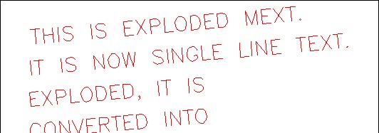
Using The EXPLODE command, as shown below, explode the mtext object at the top of the drawing only. When exploded, mtext is converted into single line text. Do not explode the lower mtext object. (Figure Step 8)
Command: EXPLODE
Select objects: 1 found
Select objects:
Command:
Step 9
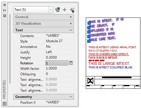
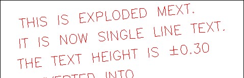
Open the Properties window and then select the five lines of text. While the text lines are selected, set the rotation angle to 5 degrees and the height of 0.3. Using what you learned in Module 19, edit the first two lines of the text to match the figure. (Figure Step 9A and 9B)
Step 10
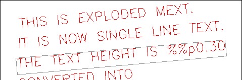
Edit the third line of text. Add the special characters ‘ %%p ‘ preceding the number 0.30 and execute the command. Your drawing should appear as shown in the figure. (Figure Step 10A and 10B)
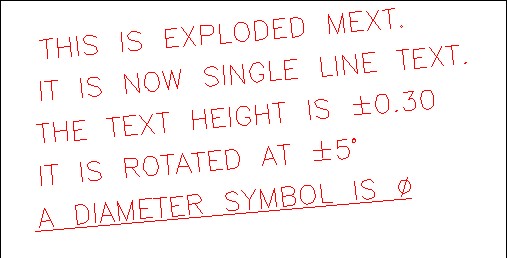
Step 11
Using what you just learned and the special character table in Figure 25-3, edit the text to appear as shown in the figure. (Figure Step 11)
Step 12
Your finished drawing should appear as shown in the figure. (Figure Step 12)
Step 13
Save and close the drawing.
Key Principles
Key Principles in Module 25
- Unlike single line text, multiline text is a text object that can contain one or more lines of text and is one drawing object.
- There are two basic font types available in AutoCAD. They are shape fonts and true type fonts.
- Shape fonts are vector fonts and true type fonts are raster fonts.
- Not all characters or symbols are available on a keyboard. These characters are called special characters. To enter them as text, the control codes ‘ %% ‘ must precede the special character.
Lab Exercise 25-1
Time allowed: 45 minutes.
| Drawing Name | Template | Units |
|---|---|---|
| AutoCAD 2D Lab 25-1 | 2D Layout English | Inches |
Step 1
Create a text style named: Module Lab 25, font: Romans. Set it as the current text style.
Step 2
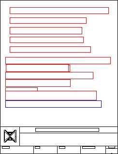
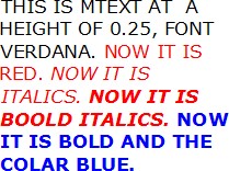
Set layer: Text as the current layer. Enable layout: Module Layout A. In Paper space, insert 4 mtext objects as shown in the figure. Leave the spelling errors in the text as you enter it. Locate the text by eye to match the figure the best you can. (Figure step 2)
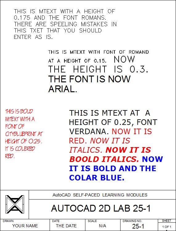
Note: Not all computer systems have the same fonts loaded. This is especially true for true type fonts. If you don’t have the font requested in a lab exercise, choose another one of your choice.
Step 3
Complete the titleblock using the AutoCAD book Titleblock Standards shown in Module 20.
Lab Exercise 25-2 Part B
Time allowed: 45 minutes.
| Drawing Name | Template | Units |
|---|---|---|
| AutoCAD 2D Lab 25-2 | N/A | Inches |
Step 1
Open the drawing: AutoCAD 2D Lab 25-1. Using the SAVEAS command, save and name it: AutoCAD 2D Lab 25-2.
Step 2
Spell check all text in the layout and correct all spelling errors.
Step 3
Explode the mtext that is shown in Figure Step 3 only.
Step 4
Edit the text to appear as shown in Figure Step 4.
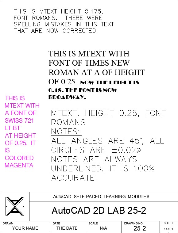
Note: Not all computer systems have the same fonts loaded. This is especially true for true type fonts. If you don’t have the font requested in a lab exercise, choose another one of your choice.
