Part 8
Module 38: Dimensioning – Part 2
Learning Outcomes
When you have completed this module, you will be able to:
- Describe the six basic dimensioning types.
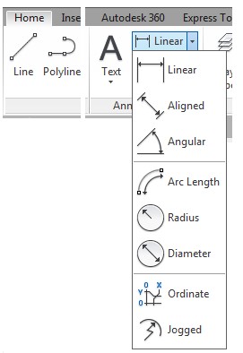
- Apply the DIMLINEAR, DIMALIGNED, DIMANGULAR, DIMDIAMETER, DIMRADIUS, and QLEADER commands to dimension a drawing.
- Edit inserted dimensions using the Properties window.
Drafting Lesson Basic Dimension Types
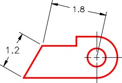
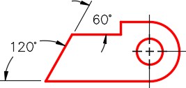
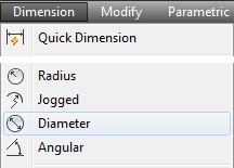
Figure 38-1 shows the six basic dimension types that will be taught in this module. They are the linear, aligned, angular, diameter, radius, and leader dimensions.
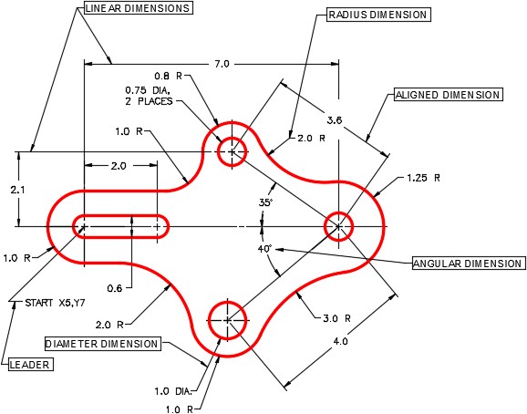
Basic Dimensioning Types
Inserting Dimensions
In this module, inserting and editing linear, aligned, angular, radius, diameter, and leader dimensions will be taught. When a dimension is inserted, it resides on the current layer and assumes the color of that layer.
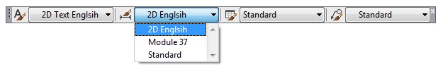
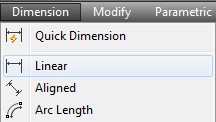
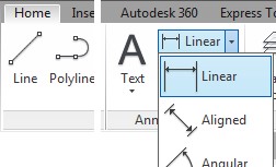
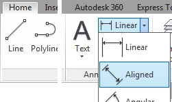
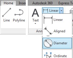
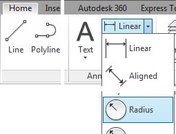
USER TIP: The current dimensioning style will appear in the Dimensioning toolbar, the Styles toolbar, and Home ribbon. A quick way to check or change the current dimensioning style is with one of these drop-down menus. Try to get into the habit of using the Dimensioning toolbar or the Home ribbon to insert dimensions. It will speed your drawing productivity.

MUST KNOW: Before dimensioning a drawing, it is important to check the following settings:
- The current layer. That is the layer that the inserted dimensions will reside on.
- The current dimensioning style. The dimensions that you insert, with any dimensioning command, will use the properties of the current dimensioning style.
- The DIMASSOC setting. This setting controls whether the inserted dimensions will be inserted as associative dimensions or exploded dimensions.
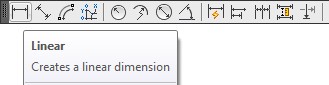
AutoCAD Command: DIMLINEAR
The DIMLINEAR command is used to insert a linear dimension. A linear dimension is a dimension that is either horizontal or vertical.
Shortcut: DIMLIN
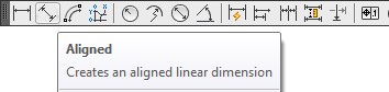
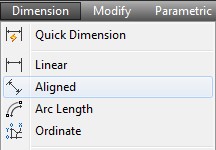
AutoCAD Command: DIMALIGNED
The DIMALIGNED command is used to insert an aligned dimension.
Shortcut: DIMALI
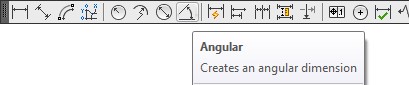
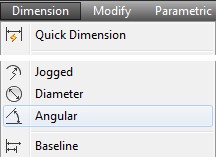
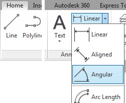
AutoCAD Command: DIMANGULAR
The DIMANGULAR command is used to insert an angular dimension.
Shortcut: DIMANG
AutoCAD Command: DIMDIAMETER
The DIMDIAMETER command is used to insert a diameter dimension.
Shortcut: DIMDIA

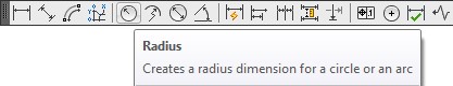
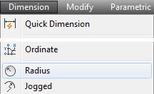
AutoCAD Command: DIMRADIUS
The DIMRADIUS command is used to insert a radius dimension.
Shortcut: DIMRAD
WORKALONG: Inserting Linear, Aligned, Angular, Diameter and Radius Dimensions
Step 1
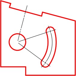
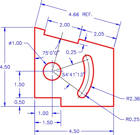
Open the drawing: AutoCAD 2D Workalong 37-1. (Figure Step 1)
Step 2
Using the SAVEAS command, save and name the drawing: AutoCAD 2D Workalong 38-1.
Step 3
Enter the DIMASSOC system variable, as shown below, and ensure that it is set to 2. This will enable associative dimensions.
Command: DIMASSOC
Enter new value for DIMASSOC <1>: 2
Command:
Step 4
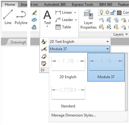
Enable the display of the Dimension toolbar. Set the current dimensioning style to: Module 37. (Figure Step 4)

Step 5
Set layer: Dimensions as the current layer and set Paper space as the current space.
Step 6
Delete the center lines for the circle. (Figure Step 6)
Step 7
Turn layer: Center Lines off.
Step 8
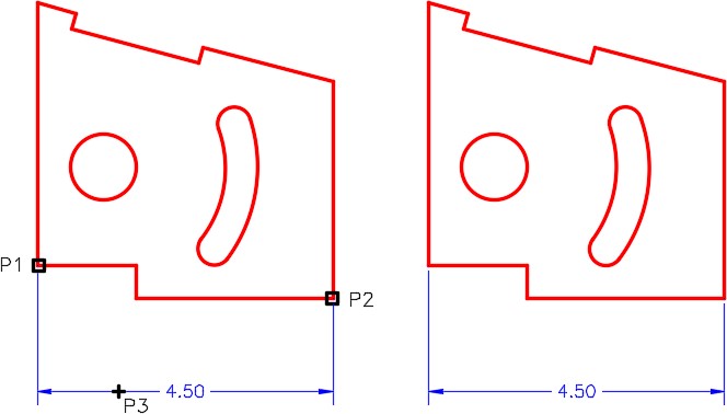
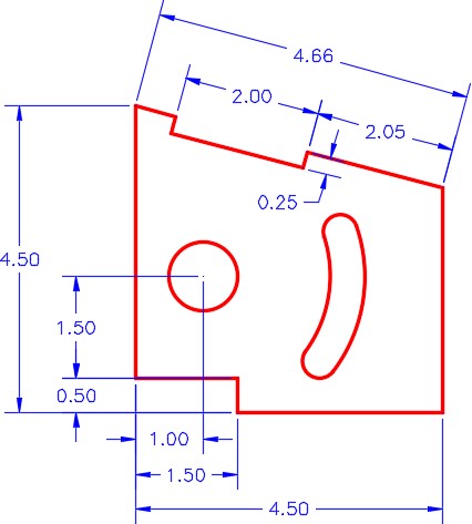
Enter the DIMLIN command, as shown below, to insert a linear dimension. (Figure Step 8)
Command: DIMLIN
Specify first extension line origin or <select object>: (end) P1
Specify second extension line origin: (end) P2
(Ensure to snap to the ends of the lines.)
Specify dimension line location or [Mtext/Text/Angle/Horizontal/Vertical/Rotated]: P3
(You can place the location of P3 by eye. Try to match the figure the best you can.)
Dimension text = 4.50
Command:
Step 9
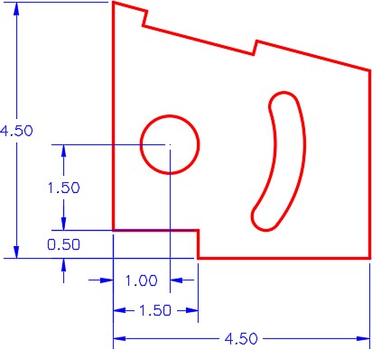
Using what you just learned, add the linear dimensions to match the figure. (Figure Step 9)
Step 10
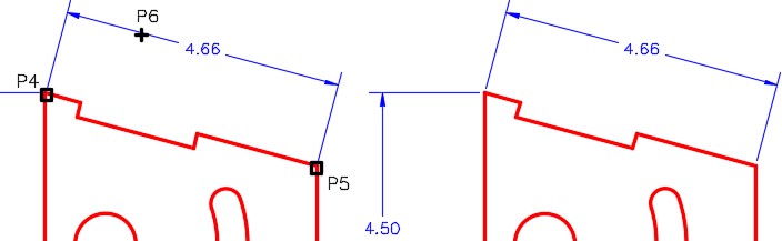
Enter the DIMALI command, as shown below, to insert an aligned dimension. (Figure Step 10)
Command: DIMALI
Specify first extension line origin or <select object>: (end) P4
Specify second extension line origin: (end) P5
Specify dimension line location or [Mtext/Text/Angle]: P6
Dimension text = 4.66
Command:
Step 11
Using what you just learned, add the aligned dimensions to match the figure. (Figure Step 11).
Step 12
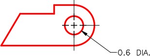
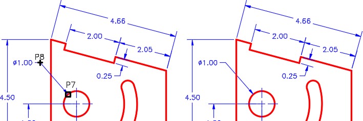
Enter the DIMDIA command, as shown below, to insert a diameter dimension as shown in the figure. (Figure Step 12)
Command: DIMDIA
Select arc or circle: P7
Dimension text = 1.00
Specify dimension line location or [Mtext/Text/Angle]: P8
Command:
Step 13
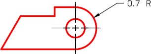
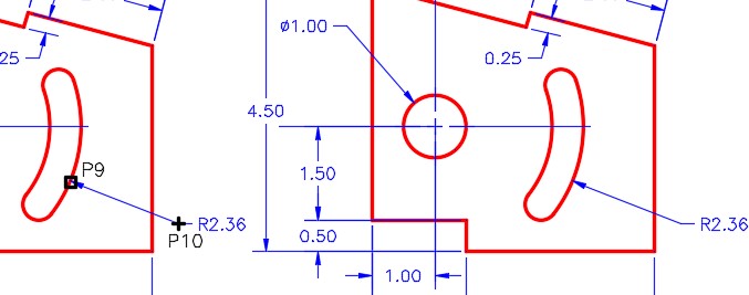
Enter the DIMRAD command, as shown below, to insert a radius dimension. (Figure Step 13)
Command: DIMRAD Select arc or circle: P9
Dimension text = 2.56
Specify dimension line location or [Mtext/Text/Angle]: P10
Command:
Step 14
Using what you just learned, add a second radius dimension to match the figure. (Figure Step 14)
Step 15
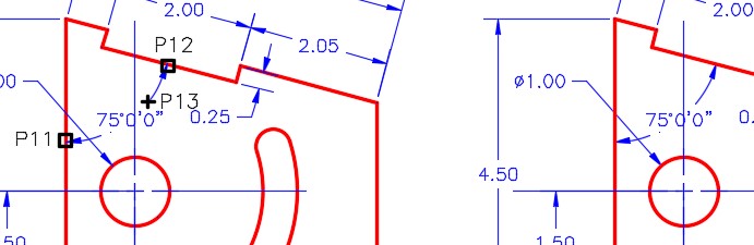
Enter the DIMANG command, as shown below, to insert an angular dimension. (Figure Step 15)
Command: DIMANG
Select arc, circle, line, or <specify vertex>: P11
Select second line: P12
Specify dimension arc line location or [Mtext/Text/Angle]: P13
Dimension text = 75d0’0″
Command:
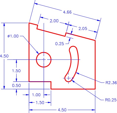
Step 16
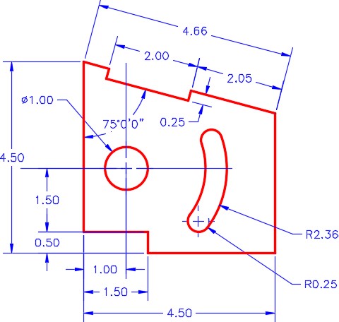
Your drawing should be similar to the figure. (Figure Step 16)
Step 17
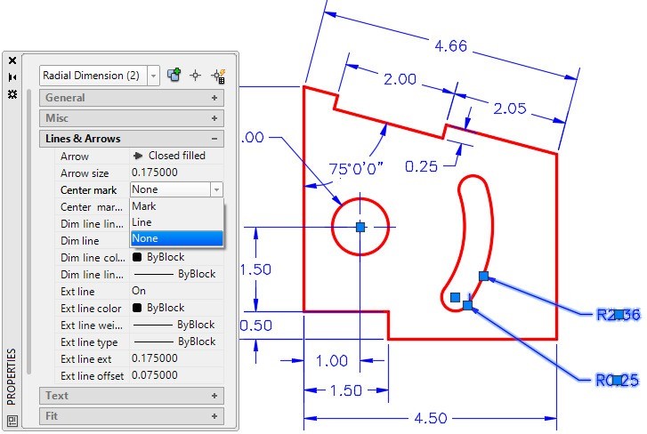
Open the Properties window. Select the two radius dimensions shown in the figure. Set the Center mark property to None. (Figure Step 17)
Step 18
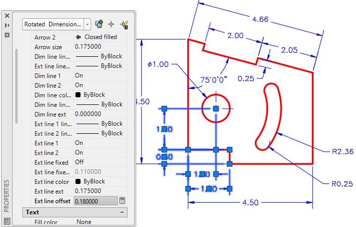
Select the two linear dimensions shown in the figure. Set the Ext line offset property to 0.1800. (Figure Step 18)
Step 19
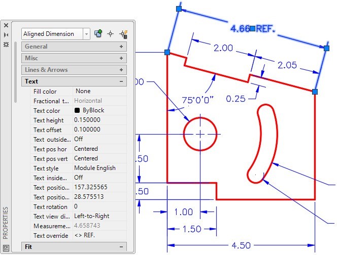
Select the aligned dimension shown in the figure. Set the Text override property to < > REF. (Figure Step 19)
Step 20
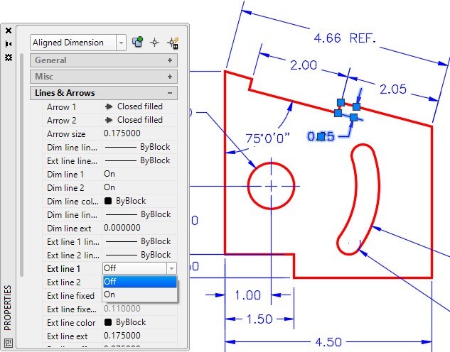
Select the aligned dimension shown in the figure. Change the property Ext Line 2 to Off. This will turn off the display of one of the extension lines since it is on object line. Depending on the order that you used when inserting the dimension, you may have to set Ext Line 1 instead. (Figure Step 20)
Step 21
Turn layer: Center Lines on. Your drawing should match the figures. (Figure Step 21)
Step 22
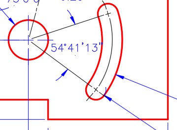
Using what you learned earlier, insert the angular dimension as shown in the figure. (Figure Step 22)
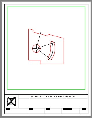
Step 23
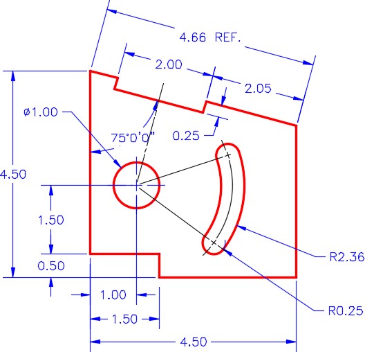
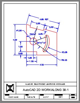
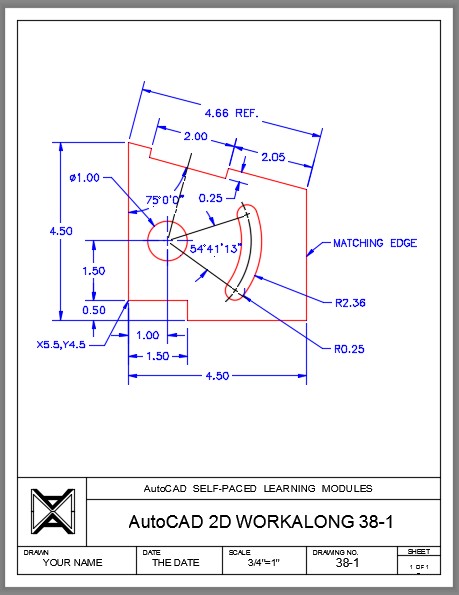
Your drawing should closely match the figure. (Figure Step 23A and 23B)
Step 24
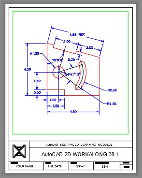
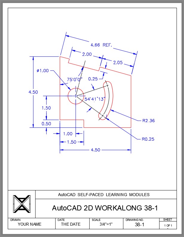
Turn layer: Viewport off. Fill in the titleblock. (Figure Step 24)
Step 25
Save and close the drawing.
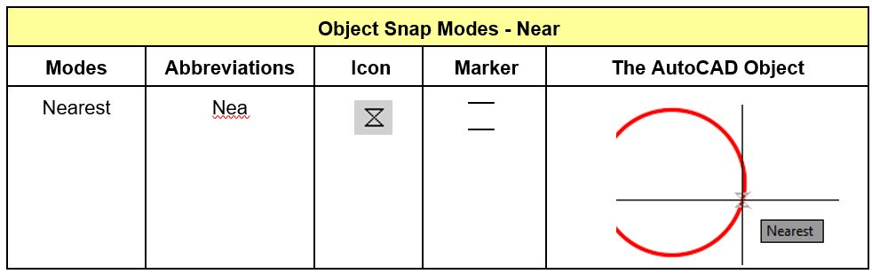
Object Snap Mode – Near
AutoCAD Command: QLEADER
The QLEADER command is used to a leader dimension.
Shortcut: none
USER TIP: The snap mode nearest can be used for many purposes while drawing in AutoCAD. To snap to an object, but not any particular location on that object, use the nearest snap mode. It is best to manually type the near snap mode, when required, rather then including it in the Autosnap settings. i.e.
Command: LINE
Specify first point: near to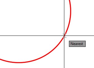
WORKALONG: Inserting Leaders
Step 1
Open the drawing: AutoCAD 2D Workalong 38-1. (Figure Step 1)
Step 2
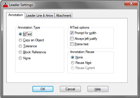
Enter the QLEADER command, as shown below, and enter the Settings option. It will open the Leader Settings dialogue box. Enable the Annotation tab. Ensure that the dialogue box matches the settings in the figure. (Figure Step 2)
Command: QLEADER
Specify first leader point, or [Settings]: S
Command:
Step 3
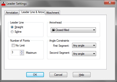
Enable the Leader Line and Arrow tab. Ensure that your dialogue box matches the settings in the figure. (Figure Step 3)
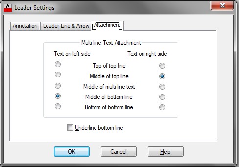
Step 4
Enable the Attachment tab. Ensure that your dialogue box matches the settings in the figure. (Figure Step 4)
Step 5
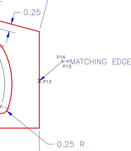
Enter the QLEADER command, as shown below, to insert the leader. (Figure Step 5)
Command: QLEADER
Specify first leader point, or [Settings] <Settings>: (near) P13
(Use the Near osnap mode)
Specify next point: P14
Specify next point: <Ortho on> P15
(I enabled Ortho mode to ensure the line is horizontal.)
Specify text width <0.0000>:
Enter first line of annotation text <Mtext>: MATCHING
Enter next line of annotation text <Mtext>: EDGE
Enter next line of annotation text:
Command:
Step 6
Using what you just learned, add the leader START X5.5Y4.5 as shown in the figure. Your completed drawing shown now appear similar to the figure. (Figure Step 6)
Step 7
Save and close the drawing.
Key Principles
Key Principles in Module 38
- When AutoCAD finds the dimension or measures the object in a dimensioning command, it does not display the actual number. The symbol <> is displayed. This symbol means default or the actual measurement.
- To make corrections to inserted associative dimensions, change the properties of the dimension using the Properties window.
Lab Exercise 38-1
Time allowed: 30 minutes.
| Drawing Name | Template | Units |
|---|---|---|
| AutoCAD 2D Lab 38-1 | N/A | Inches |
Step 1
Open the drawing: AutoCAD 2D Lab 37-1. Using the SAVEAS command, save and name it: AutoCAD 2D Lab 38-1.
Step 2
Set the current dimension style to: 2D English.
Step 3
Ensure that associate dimensioning is enabled by checking the setting of the DIMASSOC system variable.
Step 4
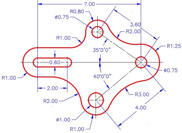
In Paper space, on layer: Dimensions, insert the dimensions shown in the figure. Match the figure the best you can. (Figure step 4A and 4B)
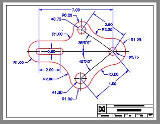
Completed Drawing
Step 5
Turn layer: Viewport off.
Step 6
Using the standards in Module 20, complete the titleblock.
Lab Exercise 38-2
Time allowed: 30 minutes.
| Drawing Name | Template | Units |
|---|---|---|
| AutoCAD 2D Lab 38-2 | N/A | Millimeters |
Step 1
Open the drawing: AutoCAD 2D Lab 37-2. Using the SAVEAS command, save and name it: AutoCAD 2D Lab 38-2.
Step 2
Set the current dimension style to: 2D Metric.
Step 3
Ensure that associate dimensioning is enabled by checking the setting of the DIMASSOC system variable.
Step 4
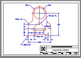
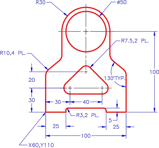
In Paper space, on layer: Dimensions, insert the dimensions shown in the figure. Match the figure the best you can. Figure step 4A and 4B)
Step 5
Turn layer: Viewport off.
Step 6
Using the standards in Module 20, complete the titleblock.
Lab Exercise 38-3
Time allowed: 40 minutes.
| Drawing Name | Template | Units |
|---|---|---|
| AutoCAD 2D Lab 38-3 | N/A | Inches |
Step 1
Open the drawing: AutoCAD 2D Lab 37-3. Using the SAVEAS command, save and name it: AutoCAD 2D Lab 38-3.
Step 2
Set the current dimension style to: 2D English.
Step 3
Ensure that associate dimensioning is enabled by checking the setting of DIMASSOC.
Step 4
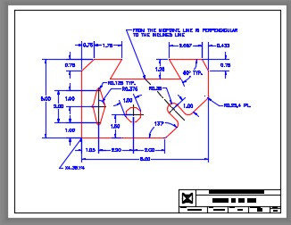
In Paper space, on layer: Dimensions, insert the dimensions shown in the figure. Match the figure the best you can. (Figure step 4A and 4B)
Step 5
Turn layer: Viewport off.
Step 6
Using the standards in Module 20, complete the titleblock.
