Part 4
Module 19: Text – Part 1
Learning Outcomes
When you have completed this module, you will be able to:
1 Describe single line text, text style, and text justification.
2 Apply the STYLE, TEXT, and DDEDIT commands to format, insert, and edit single line text.
Text
In this module, formatting, inserting, and editing single line text is taught. Single line text is text that is inserted as a single line, is edited one line at a time, and each line is a individual drawing object. Module 25 teaches multiline text.
Text Style
The STYLE command is used to create and format text styles plus used to set the current text style. A text style contains text properties, is user created, named, and saved in the drawing. As many text styles as required can be created and saved in each drawing. The current text style is the text style that will be assigned to text that is inserted in the drawing using the TEXT command.
A good example to explain text style is to use the text font. Font is a text property that is set in a text style. If you want to change the font of an existing text object on the drawing, the style property of the text must be changed. This is done using Properties window. Simply find the text style assigned to the selected text and then change the font property of that style. All existing text, with that style, will change to reflect the new font assigned. If you only want to change the font of the selected text, defined a new text style with the font required and change the style assigned to the selected text.
All AutoCAD drawings contain a text style named Standard. It is special style that cannot be deleted or purged from the drawing. It should not be used as it may cause problems in the drawing sometime in the future. The reason for this will be taught later in the book. For now, create your own text style or use ones that already exist.
Text Justification
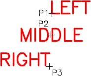
Text justification is a property attached to text objects that locates the text in relation to its insert point selected by the you in the TEXT command. There are many ways to justify text and it is important for you to know how, where, and when to use each one. In this module, the left, middle, and right justified text are taught. Figure 19-1 shows how a text object would justify itself if inserted at the selected locations P1, P2, and P3. If you do not specify a justification when inserting text, the default justification is left.
Text Height
Text height is a property assigned to the text drawing object and not to the text style. In almost all cases, the text height property, in the text style, should be set to zero. When it is set to zero, AutoCAD allows you to change the text height of text inserted with that style. It also allows the text style to automatic scale text in a dimension.
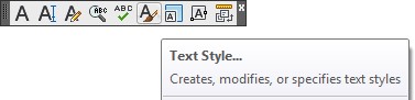
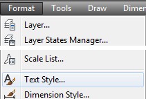
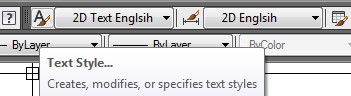
AutoCAD Command: STYLE
The STYLE command is used to create, format, and edit text styles. It also is used to set the current text style.
Shortcut: ST
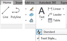
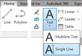
Home Ribbon
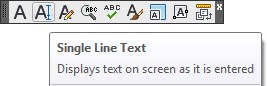
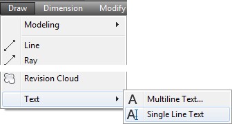
AutoCAD Command: TEXT
The TEXT command is used to insert single line text.
Shortcut: TE
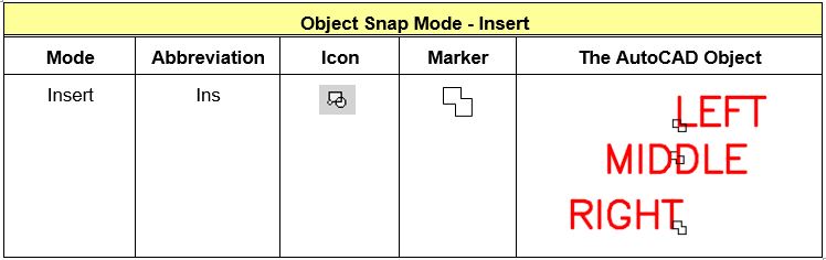
Object Snap Mode – Insert
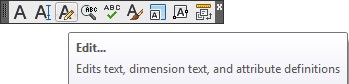
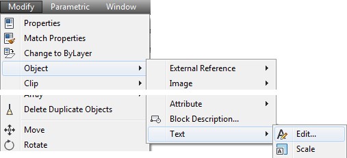
AutoCAD Command: DDEDIT
The DDEDIT command is used to edit existing text objects.
Shortcut: Double click the text.
WORKALONG: Creating Text Styles and Inserting Single Line Text
Step 1
Start a new drawing using the template: 2D Layout English.
Step 2
Save and name the drawing: AutoCAD 2D Workalong 19-1.
Step 3
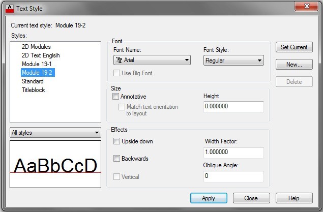
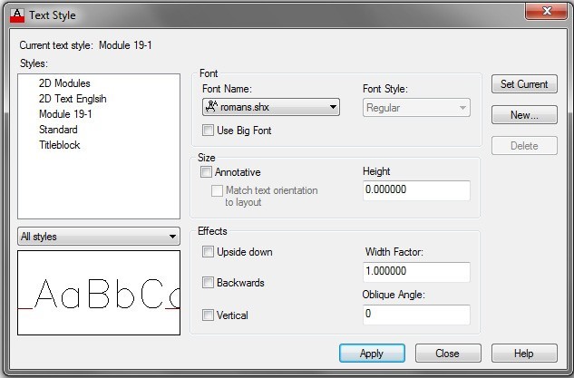
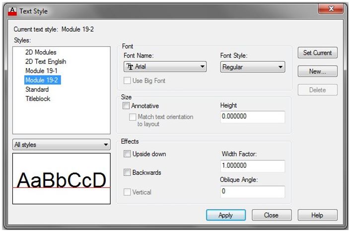
Enter the STYLE command. It will open the Text Style dialogue box. (Figure Step 3)
Step 4
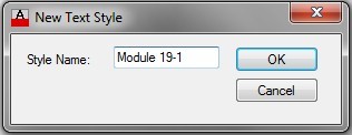
Click the New button to open the New Text Style dialogue box. (Figure Step 4)
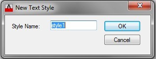
Step 5
Enter the name: Module 19-1 in the Style Name box as shown in the figure. Click OK to save and close the dialogue box. (Figure Step 5)
Step 6
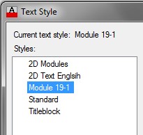
Check to ensure that the Current text style is set to: Module 19-1. (Figure Step 6)
Step 7
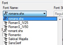
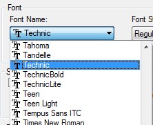
In the Font Name: box, pull down the list and select the font: romans.shx. (Figure Step 7)
Step 8
Do not change any other items. The Text Style dialogue box should now appear as shown in the figure. Click the Close button to save and close the dialogue box. (Figure Step 8)
Step 9
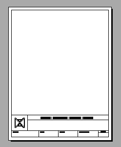
Enable layout: Module Layout A. (Figure Step 9)
Step 10
Set layer: Text as the current layer.
Step 11
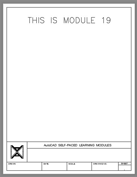
Enter the TEXT command, as shown below, to insert text on the drawing. (Figure Step 11)
Command: TEXT
Current text style: “Module 19-1” Text height: 0.2000
(The defaults will display. Ensure that Module 19-1 is the current default style.)
Specify start point of text or [Justify/Style]: 1,9
(This is the insert point. By default, the text will be left justified)
Specify height <0.2000>: 0.35
Specify rotation angle of text <0>:
(Press Enter to leave the rotation angle at 0 degrees.)
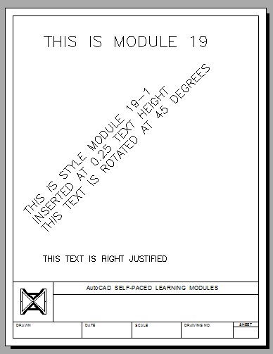
THIS IS MODULE 19
(Type the text and press Enter)
(Press Enter again)
Command:
Step 12
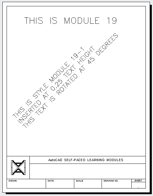
Enter the TEXT command, as shown below, to insert text on the drawing. (Figure Step 12)
Command: TE
Current text style: “Module 19-1” Text height: 0.3500 Specify start point of text or [Justify/Style]: 0.5,3.5 Specify height <0.3500>: 0.25
Specify rotation angle of text <0>: 45
THIS IS STYLE MODULES 19-1
(Press Enter)
INSERTED AT 0.25 TEXT HEIGHT
(Press Enter)
IT IS ROTATED AT 45 DEGREES
(Press Enter)
Command:
Step 13
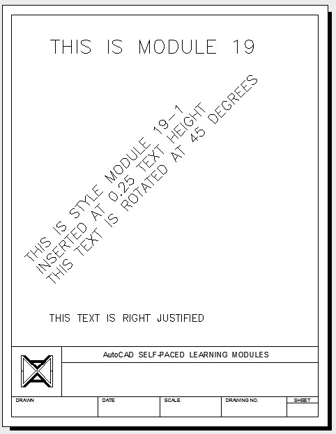
Enter the TEXT command, as shown below, to insert text on the drawing. (Figure Step 13)
Command: TE
Current text style: “Module 19-1” Text height: 0.0250
Specify start point of text or [Justify/Style]: J
Enter an option [Align/Fit/Center/Middle/Right/TL/TC/TR/ML/MC/MR/BL/BC/BR]: R
(Setting a right justification.)
Specify right endpoint of text baseline: 5,2
Specify height <0.2500>: 0.175
Specify rotation angle of text <45>: 0
THIS TEXT IS RIGHT JUSTIFIED. (Press Enter)
Command:
Step 14
Save and close the drawing.
WORKALONG: Editing Single Line Text
Step 1
Open the drawing: AutoCAD 2D Workalong 19-1.
Step 2
Using the SAVEAS command, save it with the name: AutoCAD 2D Workalong 19-2.
Step 3
Using what you learned in the first workalong, enter the STYLE command and create a new text style named: Module 19-2. Set the text style to match the figure. (Figure Step 3)
Step 4
Enable the display of layout: Module Layout A. (Figure Step 4)
Step 5
Double click the text at the top of the drawing to enter edit mode. (Figure Step 5)

Step 6
With the text in edit mode, change the text to read THIS IS EDITED TEXT. (Figure Step 6)

USER TIP: If the text editor does not open when you double click the text object, enter the DBLCLKEDIT system variable, as shown below, and set to ON.
Command: DBLCLKEDIT
Enter new value for DBLCLKEDIT <OFF>: ON
Command:
Step 7
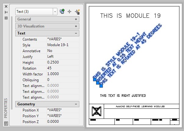
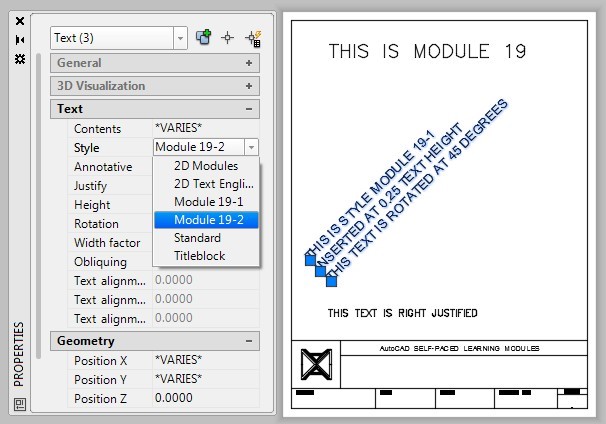
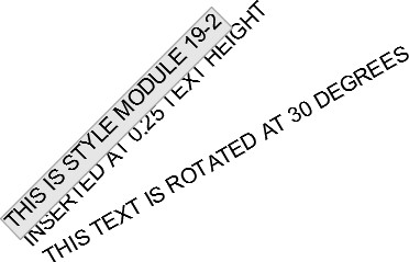
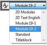
Open the Properties window. Select the three lines of text as shown in the figure. While the text is selected, pull-down the Style property list and select layout: Module 19-2. Press Enter and then Esc to clear the selected text. (Figure Step 7A and 7B)
Step 8
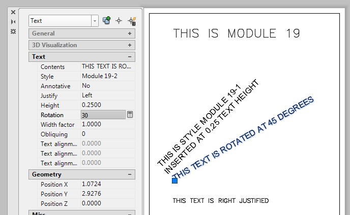
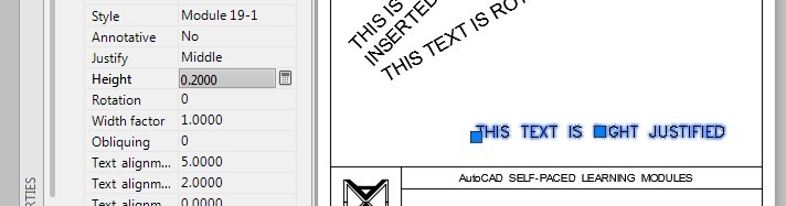
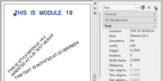
Select the bottom line of the rotated text as shown in the figure. In the Properties window, change the Rotation angle property to 30. (Figure Step 8)
Step 9
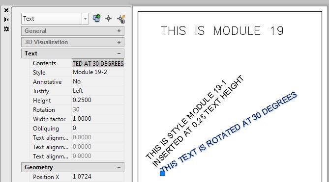
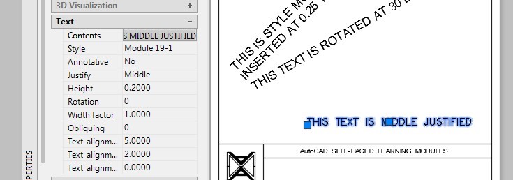
While the text is selected, change the Contents property as shown in the figure. (Figure Step 9)
Step 10
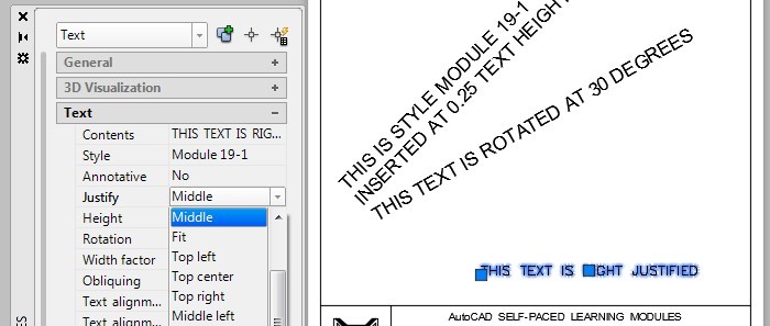
Select the bottom text line. In the Properties window, change the Justification property to Middle, the Height property to 0.2, and the Contents property as shown in the figure. (Figure Step 10A, 10B, and 10C)
Step 11
Double click the text and edit it as shown in the figure. (Figure Step 11)
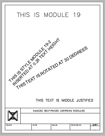
Step 12
Your completed layout should appear as shown in the figure. (Figure Step 12)
Step 13
Save and close the drawing.
USER TIP: When using a pull down window with lists, such as the font list in the Text Style dialogue box, and you know the name of the font you want to use, enter the first letter of the font after you pullthe list down. The list will jump to the font names that start with that letter. This should work for all software written to Window’s standards.
Key Principles
Key Principles in Module 19
- Single line text is text that is inserted as a single line, can be edited one line at a time, and each line is its own drawing object.
- The text style defines the text properties, like the font and width of the text. To change the font of a text, its style property must be changed.
- The text height should almost always be set to zero in the Text Style dialogue box.
- The Standard text style is a special text style that is contained in every drawing. It cannot be deleted or purged. It is best not to use this text style in your drawings.
- The text height, style, rotation angle, content, justification, width factor, and obliquing angle are text properties and can be changed in the Properties window.
- To edit text, double click it. This will automatically open the Edit Text dialogue box with the selected text, ready to be edited. This is a very fast way to edit single line text and almost eliminates the use of the DDEDIT command. Text contents can also be edited in the Properties window.
Lab Exercise 19-1
Time allowed: 60 minutes.
| Drawing Name | Template | Units |
|---|---|---|
| AutoCAD 2D Lab 19-1 | 2D Layout English | Inches |
Step 1
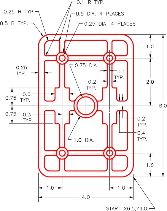
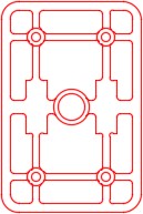
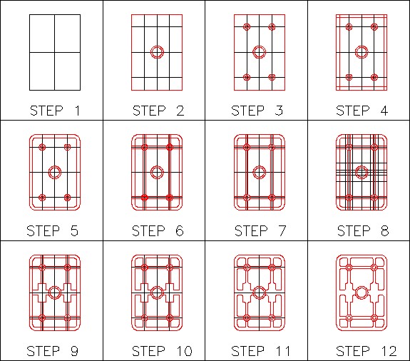
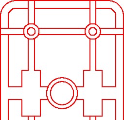
On layer: Object, draw the object shown in the figure. (Figure Step 1A and 1B)
Step 2
Draw all construction objects on layer: Construction.
Step 3
Set the insertion units and insert the key. Check the drawing for accuracy.
Step 4
Turn layer: Key off and freeze layer: Construction.
Step 5
In layout: Module Layout A, on layer: Viewport, create a viewport using the MVIEW command. Pan the model as shown in the figure. Set the scale to 1:1 and lock the display. (Figure Step 5)
Step 6
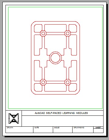
In layout: Module Layout B, on layer: Viewport, create two viewports using the MVIEW command. Pan the model as shown in the figure and set the custom scale of the left viewport to 1.5:1 and the one on the right to 4:1. Lock the display of both viewports. (Figure Step 6)
Step 7
Turn layer: Viewport off. (Figure Step 7)
Step 8
Save and close the drawing.
Hint 1
Once you have drawn the outer boundary and the inner construction lines (Step 3 above), use the OFFSET command to construct most of the remaining drawing.
Hint 2
Before you insert the fillets, trim the lines as shown in the figure. If you do not trim them first, you will lose portions of the lines when you insert the fillets. Always insert the fillets last. (Figure Hint 2)
Lab Exercise 19-2
Time allowed: 40 minutes.
| Drawing Name | Template | Units |
|---|---|---|
| AutoCAD 2D Lab 19-2 | 2D Layout English | Inches |
Step 1
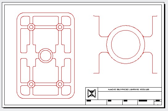
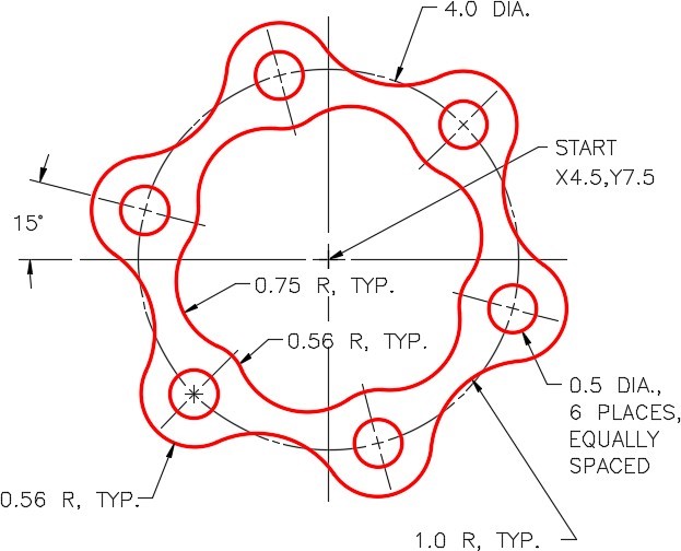
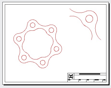
On layer: Object, draw the object shown in the figure. (Figure Step 1A and 1B)

Step 2
Draw all construction objects on layer: Construction.
Step 3
Set the insertion units and insert the key. Check the drawing for accuracy.
Step 4
Turn layer Key off and freeze layer: Construction.
Step 5
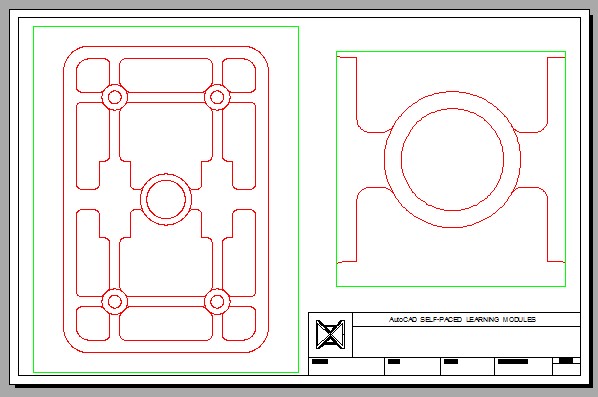
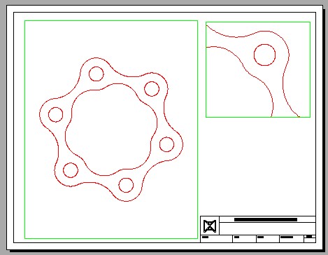
In layout: Module Layout C, on layer: Viewport, create two viewports using the MVIEW command. Pan the model as shown in the figure. Set the custom scale of the left viewport to 2:1 and the one on the right to 3:1. Lock the display of both viewports. (Figure Step 5)
Step 6
Turn layer: Viewport off. (Figure Step 6)
Step 7
Save and close the drawing.
Hint 1
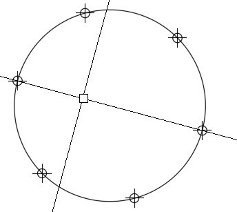
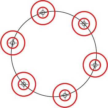
Rotate the cursor to -15 degrees before dividing the circle. Draw six 0.5 diameter and 1.12 diameter circles using the points as their center locations. (Figure Hint 1A and 1B)
Hint 2
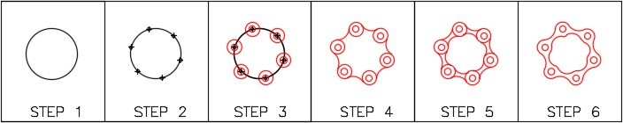
See the following steps:
Step 1 – Insert 1.0 radius fillets.
Step 2 – Insert 0.75 radius fillets.
Step 3 – Trim the circles.
(Figure Step Hint 2)

Figure Hint 2
