Part 2
Module 9: Arraying and Mirroring 3D Models
Learning Outcomes
When you have completed this module, you will be able to:
- Apply the 3DARRAY and MIRROR3D commands to construct and modify 3D models.
Modifying 3D Objects
When constructing 3D models, the only time the 2D commands ARRAY and MIRROR can be used is if all the objects that are selected in the command lie on the 2D plane of the current UCS. To array or mirror objects in 3D space, the corresponding 3D commands must be used.
3D Array
A 3D array, using the 3DARRAY command, is very similar to a 2D array, using the ARRAY command, that was taught in the AutoCAD 2D book. A rectangular and a polar 3D array can be preformed.
Rectangular Array
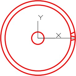
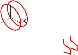
A 2D rectangular array uses rows and columns. In 3D, the third dimension of the array is called a level. Rows are along the Y axis, columns are along the X axis and levels are along the Z axis. Distance between the rows, columns and levels can be positive or negative. See Figure 9-1.
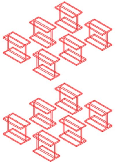
3D Rectangular Array
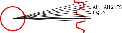
Polar Array
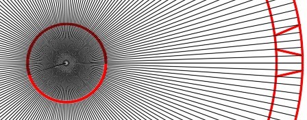
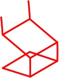
A 2D polar array only requires a XY point to array around while a 3D polar array, two XYZ points, a line or an axis must be specified to array around. See Figure 9-2.
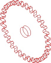
3D Polar array
3D Mirroring
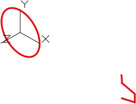
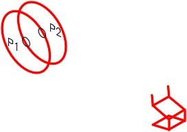
A 3D mirror, using the MIRROR3D command, is very similar to a 2D mirror, using the MIRROR command, that was taught in the AutoCAD 2D book. A 2D mirror requires two XY points or a line to mirror around while a 3D mirror requires three XYZ points or a plane to mirror around. See Figure 9-3.
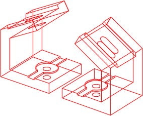
3D Mirror
AutoCAD Command: 3DARRAY
The 3DARRAY command is used to array an object(s) in 3D space.
Shortcut: none
AutoCAD Command: MIRROR3D
The MIRROR3D command is used to mirror an object(s) in 3D space.
Shortcut: none
WORK ALONG: Creating a 3D Rectangular Array
Step 1
Using the NEW command, start a new drawing using the template: 3D Layout English.
Step 2
Save and name the drawing: AutoCAD 3D Workalong 09-1.
Step 3
Set layer: Model as the current layer.
Step 4
Using the figures as a reference, draw the wireframe model. Note the location of the WCS. (Figure Step 4A and 4B)
Right Side View
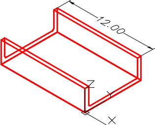
Wireframe Model
Step 5
Using the figures as a reference, draw the circle and then copy it to create a hole through the Front view. (Figure Step 5A, 5B, and 5C)
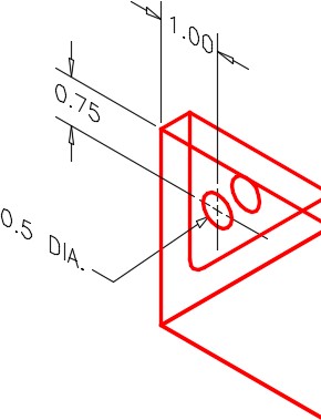
Hole Detail
Wireframe Model
Solid Model
Step 6
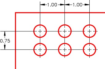
Study the figure. It shows the hole pattern that will be used in the 3D ARRAY command. (Figure step 6)
Step 7
Ensure that Osnap is disabled.
Step 8
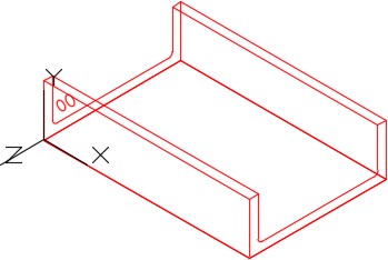
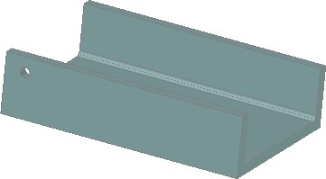
Ensure that the current UCS is set to the Front and enter the 3DARRAY command, as shown below, to array the holes. Your finished drawing should appear as shown. (Figure Step 8A and 8B)
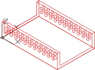
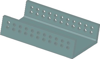
Solid Model – Rotated View
Command: 3DARRAY
Select objects:
Specify opposite corner: 2 found
(Select the two circles.)
Select objects:
Enter the type of array [Rectangular/Polar] <R>:
(Rectangular array)
Enter the number of rows (—) <1>: 2
Enter the number of columns (|||) <1>: 11
Enter the number of levels (…) <1>: 2
Specify the distance between rows (—): -0.75
(In the negative Y direction.)
Specify the distance between columns (|||): 1
(In the positive X direction.)
Specify the distance between levels (…): -7.5
(In the negative Z direction.)
Command:
WORK ALONG: Creating a 3D Polar Array
Step 1
Using the NEW command, start a new drawing using the template: 3D Layout English.
Step 2
Save and name the drawing: AutoCAD 3D Workalong 09-2.
Step 3
Draw all model objects on layer: Model and all construction objects on layer: Construction. (Figure Step 3A, 3B, and 3C)
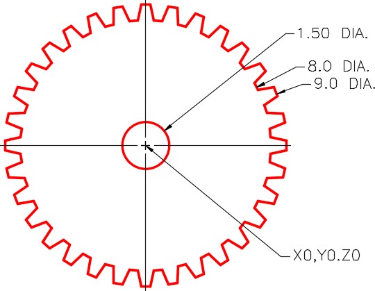
Multiview Drawing – Gear is 0.5 Inches Thick
Detail of Gear Teeth
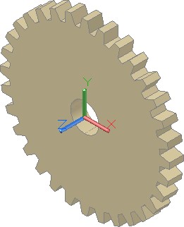
Solid Model – SE Isometric View
Step 4
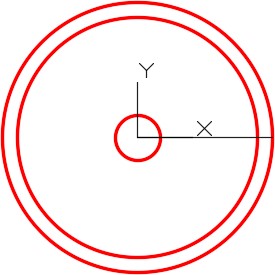
Set the current UCS to Front and change the current view to Front. Draw three circles and a construction line from the centre to the quad as shown in the figure. Take all of the sizes from the multiview drawing. (Figure Step 4)
Step 5
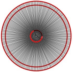
Using the ARRAY command, array the construction line 192 times around. Use the centre of the circle as the basepoint for the array. (Figure Step 5)
Step 6
On layer: Model, draw two gear teeth by drawing lines from the intersection of the lines and the circles. (Figure Step 6)
Step 7
Turn layer: Construction off and your drawing should appear as shown in the figure. (Figure Step 7)
Step 8
Trim the two outer circles to form the repeat pattern of one gear tooth. (Figure Step 8)
Step 9
Change the current view to SE Isometric. (Figure Step 9)
Step 10
Copy all objects 0.5 inches in the -Z direction. 0.5 is the thickness of the gear. (Figure Step 10)
Step 11
Add lines to complete the gear tooth. (Figure Step 11)
Step 12
Enter the 3DARRAY command, as shown below, to complete the wireframe model of the gear. (Figure Step 12A and 12B)
Command: 3DARRAY
Select objects:
Specify opposite corner: 12 found
(Select the lines that make one gear tooth in a window.)
Select objects:
Enter the type of array [Rectangular/Polar] <R>:P
(Polar array.)
Enter the number of items in the array: 32
Specify the angle to fill (+=ccw, -=cw) <360>:
(Accept the default.)
Rotate arrayed objects? [Yes/No] <Y>:
(Accept the default.)
Specify centre point of array: (cen) P1
Specify second point on axis of rotation: (cen) P2
(From centre to centre of the circles defines the endpoints of a line to be used as the axis of the array.)
Command:
Step 13
Save and close the drawing.
WORK ALONG: Creating a 3D Mirror
Step 1
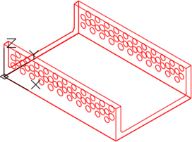
Open the drawing: AutoCAD 3D Workalong 09-1. The drawing should appear as shown in the figure. (Figure Step 1)
Step 2
Using the SAVEAS command, save the drawing with the name: AutoCAD 3D Workalong 09-3.
Step 3
Enter the MIRROR3D command, as shown below, to mirror the model. (Figure Step 3)
Command: MIRROR3D
Select objects:
Specify opposite corner: 124 found
(Select all object in the model in a window.)
Select objects:
Specify first point of mirror plane or [Object/Last/Zaxis/View/XY/YZ/ZX/3points] <3points>: (end) P1
Specify second point on mirror plane: (end) P2
Specify third point on mirror plane: (end) P3
Delete source objects? [Yes/No] <N>:
(Accept the default.)
Command:

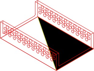
Mirror Plane
Step 4
The completed mirrored model is shown in the figure. (Figure Step 4A and 4B)
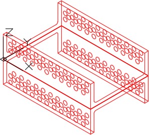
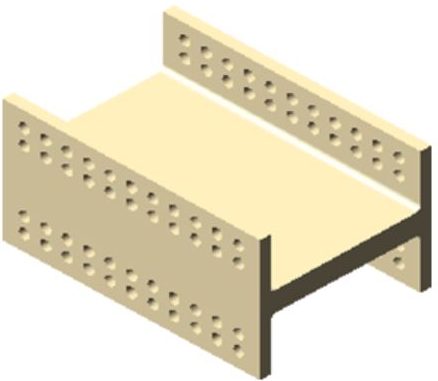
Solid Model – SE Isometric View
Step 5
Save and close the drawing.
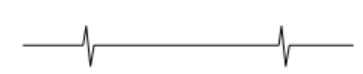
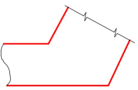
Drafting Lesson: Break Lines
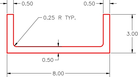
To simplify or speed up drawing orthographic views of a model, sometimes views are only partially drawn. In these cases, the cut off portion of the view is not required for the reader to visualize or construct the model. See the figures for examples of short and long break lines.
(Drawn by Eye)

(Drawn by Eye)
Key Principles
Key Principles in Module 9
- The third dimension of a 3D array is called a level.
- When rotating in 3D, you must rotate around two XYZ points or a line.
- When mirroring in 3D, you must mirror around a three XYZ points or a plane.
- Always disable object snap when executing a 3D array.
Lab Exercise 9-1
Time allowed: 50 minutes.
| Drawing Name | Template | Units |
|---|---|---|
| AutoCAD 3D Lab 09-1 | 3D Layout Metric | Millimeters |
Step 1
Draw all construction objects on layer: Construction.
Step 2
Draw all model objects on layer: Model.
Step 3
Draw a wireframe model of the object shown in the figure. (Figure Step 3A and 3B)
SE Isometric View
Dimensioned Multiview Drawing
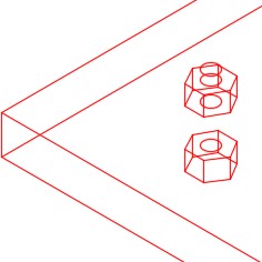
Step 4
Using the figure as a reference, anywhere in model space, draw a wireframe model of one nut and one bolt. (Figure Step 4A and 4B)
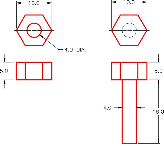
Dimensioned Multiview Drawings of Nut and Bolt
Wireframe Models of Nut and Bolt
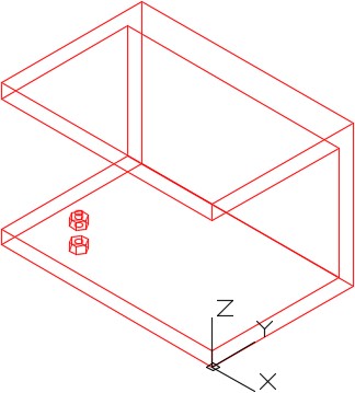
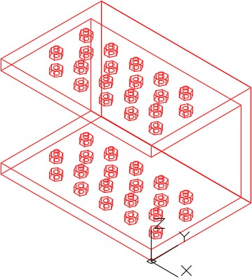
Step 5
Move one bolt and one nut to the bottom outside bolt location as shown in the figure. The bolt comes up from the bottom and nut is on top of the plane. (Figure Step 5A, 5B, 5C, and 5D)
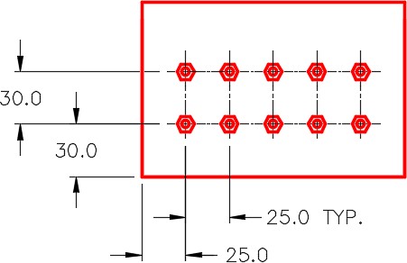
Bolt Pattern – Bottom View
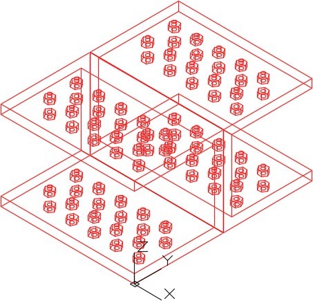
Step 6
Array the nut and bolt to match the figure. (Figure Step 6)
Step 7
Mirror the completed model. (Figure Step 7)
Step 8
Enter the UNITS command. In the Units dialogue box, set the Insertion Units to Millimeters.
Step 9
Change the current UCS to World and check the model with the key.
Step 10
Save and close the drawing.
Lab Exercise 9-2
Time allowed: 50 minutes.
| Drawing Name | Template | Units |
|---|---|---|
| AutoCAD 3D Lab 09-2 | 3D Layout English | Inches |
Step 1
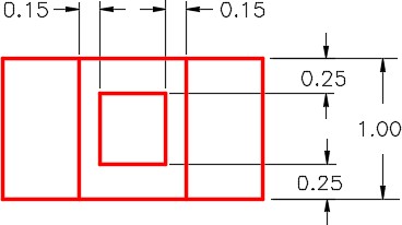
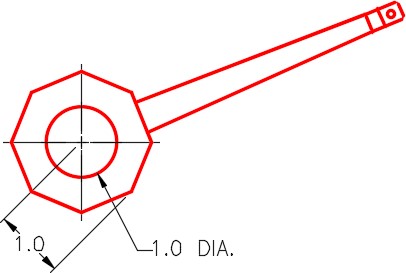
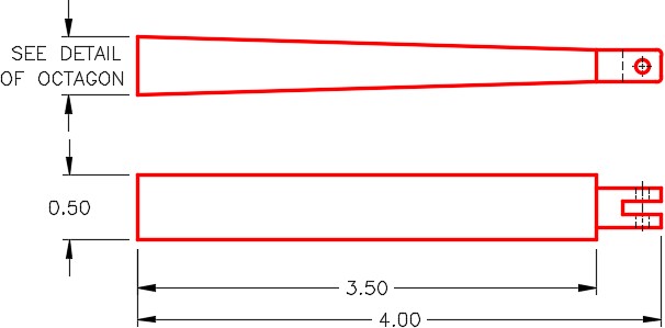
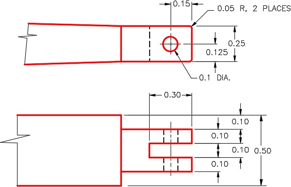
Draw a wireframe model of the centre octagon and one arm as shown in the figures. Details of the arm are in Figure Step 1D Detail B and Figure Step 1E Detail A. (Figure Step 1A, 1B, 1C, 1D, and 1E)
Step 2
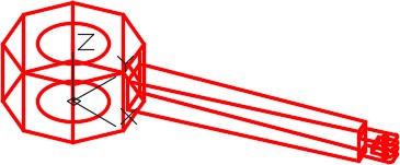
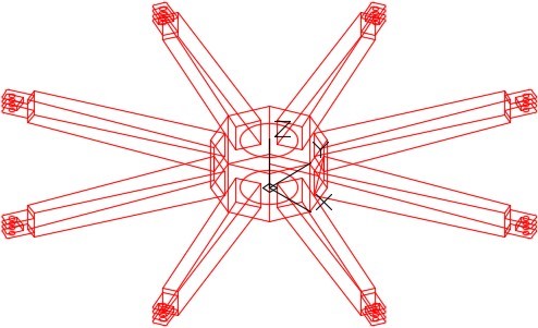
Array the arm as shown in the figure. (Figure Step 2)
Step 3
Enter the UNITS command. In the Units dialogue box, set the Insertion Units to Inches.
Step 4
Change the current UCS to World and check the model with the key.
Step 5
Save and close the drawing.
Lab Exercise 9-3
Time allowed: 50 minutes.
| Drawing Name | Template | Units |
|---|---|---|
| AutoCAD 3D Lab 09-3 | 3D Layout English | Inches |
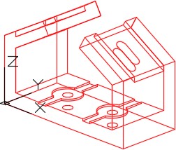
Step 1
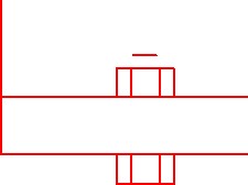
On layer: Model, draw a wireframe model as shown in the figure. See the multiview drawing in Figure 1 Step B. (Figure Step 1A and 1B)
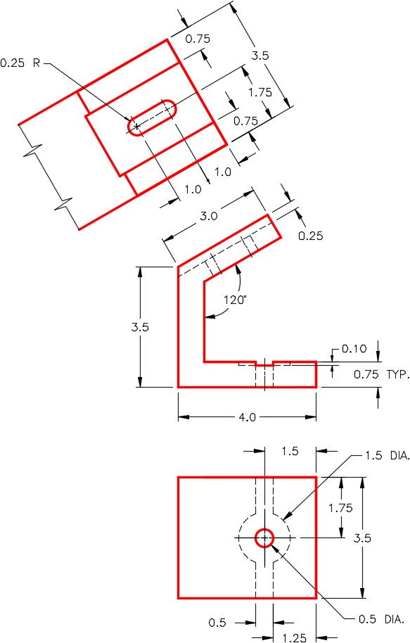
Dimensioned Multiview Drawing
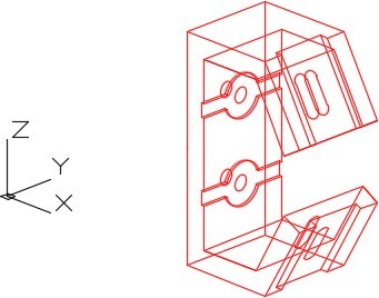
Step 2
Mirror the wireframe drawn in Step 1. Erase the extra lines and clean up the model to create one model. (Figure Step 2)
Step 3
Enter the UNITS command. In the Units dialogue box, set the Insertion Units to Inches. Change the current UCS to World and check the model with the key.
Step 4
Turn layer: Key off.
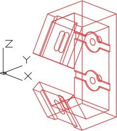
Step 5
Note the location of the UCS and rotate the model. (Figure Step 5)
Step 6
Note the location of the UCS and rotate the model. (Figure Step 6)
Step 7
Save and close the drawing.
