Introduction
Learning Outcomes
When you have completed this module, you will be able to:
- List the required software required to complete the AutoCAD 3D book.
- Describe the book’s philosophy and explain how to use the book to learn how to apply the AutoCAD commands and features to draw 3D drawings.
Software Requirements
AutoCAD Software Required
The AutoCAD 3D book was written to be used with the Windows version of AutoCAD 2015, 2016, 2017, 2018, and 2019. You must have AutoCAD 2015, 2016, 2017, 2018, or 2019 software running on your computer to complete the lab exercises in this book.
Files Required for the AutoCAD 3D book
To complete the lab exercises in this book, you must load the two template files that accompany this course onto your hard disk drive. “Configuring Your AutoCAD Software” will instruct you how to configure them and Module 2 will teach you how to use them.
About the Book
Philosophy of the AutoCAD Books
The AutoCAD books were written as a tool to guide and teach you to master AutoCAD. No two students learn at the same pace, therefore the books were written with competency-based modules. The competency-based modules are bite-size pieces that allows you to work at your own pace. They can be used to learn by distance education, correspondence, online, instructor-lead classes, or by individuals teaching themselves to use AutoCAD in their own home or office.
Scope of the AutoCAD books
The AutoCAD books were written in five parts, AutoCAD 2D, AutoCAD 3D, AutoCAD 2D Advanced, AutoCAD 3D Advanced, and AutoLISP.
Suggested Prerequisites
To get the most from this book, it is suggested that you have a working knowledge of the Windows operating system and are proficient at drawing 2D drawing objects using AutoCAD and are familiar with all commands and features used in the AutoCAD 2D book.
The AutoCAD 3D book
The modules in the AutoCAD 3D book were written in a very logical step-by-step order. The following information will help you get the most from this book.
The book Modules
This modules in the book were written as bite-size pieces in a precise order and contain the information that is required to learn AutoCAD 3D. Using AutoCAD is a never ending learning process and you will continue learning long after completing this book.
Do not skim through the modules. Read each page and ensure that everything is understood in each module. Do not jump around inside the module or from module to module. Work methodically through each module, page by page.
As you work your way through each module, try to understand all the information it contains. To ensure that it is understood, you must be able to complete the lab exercises to prove it. Only when everything in the module is understood and you can complete the lab exercises, in the specified time limit, should you go to the next module.
Book Structure and Components
Each module may contain Must Know’s, User Tips, Workalongs, Lessons, Key Principles and Lab Exercises.
Must Know’s
Most modules contain user Must Know’s. You must understand and retain each one of these principles as you work your way through the modules. If you cannot understand any one of them, read back through the module. Do not go on until you fully understand it. i.e.
(Do not attempt to understand the following Must Know, it is here for an example only.)
User Tips
User Tips are in the modules to help you to complete drawings faster and more efficiently. They contain tips, tricks and ways to use commands that will help you draw faster and increase your productivity. Study them and try to use the tips while doing your labs exercises. Don’t memorize them as you will not be tested on them. You can re-read them anytime you wish. They are there to help you work smarter, not harder. For example:
(Do not attempt to understand the following User Tip, it is here for an example only.)
USER TIP: Before you start drawing any model, you must first decide which view is the best to start with. Usually it is the view with the most difficult contour. The more practice you get modeling the easier it will be to select the best view to start your model.
Workalongs
A Workalong is an exercise you complete by working along with the modules, tutorial style, to complete the practice session that follows. Completing the workalongs in this manner will help you understand how the commands you are being taught in that module work by actually using them in AutoCAD. This will prepare you so that when you are completing the drawings in the lab exercises at the end of each module, you should be able to complete them without any assistance. For example:
(Do not attempt this workalong now, it is here for an example only.)
WORK ALONG: Polar Arraying in 3D
Step 1
Using the NEW command, start a new drawing using the template 3D Layout English.
Step 2
Save and name the drawing AutoCAD 3D Workalong 09-2.
Step 3
Create the layers Construction and Model as shown in Figure Step 3.
Geometry and Drafting Lessons
Some modules contain drafting and/or geometry lessons. They are included to teach students who do not have any previous drafting/design knowledge or experience. They may also be handy for drafters or designers who need a refresher lesson.
If you already know the theory in the lesson, skip it and go on to the next topic in the module. If you don’t know it, study it. This theory is not part of the course and you will not be tested on it.
However, knowing it will help you complete the lab exercises. For example:
(Do not try to understand the following Geometry Lesson now, it is here for an example only.)
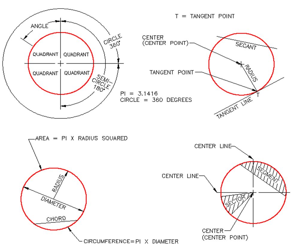
Geometry Lesson: Circles
A circle is defined as a closed curve in which all points are the same distance from its centre point. The centre point is a single XY coordinate. Study the drawings below for a complete description of the characteristics of a circle.
Key Principles
Each module contain a list of key principles. The Key Principles are principles that you should have learned and understand in the module. It is important that you understand each one of these principles as you will be required to use them in future AutoCAD work. For example:
(Do not try to learn the following Key Principles now, it is here for an example only.)
Key Principles in Module 8
- The TRIM and EXTEND commands should have the following default settings when working in 3D: Projection=None, Edge=Extend
- The ROTATE command, used for a 2D rotate, uses a point to rotate For a 3D rotate using the ROTATE3D command, a line (2 points) must be specify to rotate around or the X, Y or Z axis.
Lab Exercises
All lab exercises have a time limit allocated to them. To complete the lab exercise in the specified time limit, you must be able to complete the drawing, check it for accuracy and make any corrections. If you cannot complete it in the time allowed, redo the entire lab exercise. It is your way of proving that you have mastered the module.
Almost all modules contain at least two lab exercises. It is strongly suggested that you complete all lab exercises in the module.
Checking the Accuracy of Your Drawings
Almost all lab exercises have a key provided that you can use to check the drawing’s accuracy.
Competency Tests
Every fifth module is a timed competency test module. A Competency Test Module has multiple choice questions and a comprehensive lab exercise to test your mastery of the last set of modules completed. There is no key supplied with this module since it is meant to be checked by your instructor. If there are any parts of this module that you have trouble completing or cannot complete it in the time allowed, go back and reread the module or modules containing the information that you are having trouble with. If necessary, redo any lab exercises to help you learn the material.
Book Conventions and Symbols
The following conventions and symbols are used in the modules to help the user understand the material.
Words in Red Italics
Words in red italics are new terms being introduced in that module. They will only appear in red italics the first time they are appear and will be defined. i.e.
The current layer is the layer that AutoCAD will place all newly created drawing objects on.
Words and Numbers that are in Bold Font
In Workalongs, all words and numbers in bold font are input by the user. It is your way of knowing if it is a user input or an AutoCAD response. i.e.
Command: 3DMESH
Enter size of mesh in M direction: 5 Enter size of mesh in N direction: 4 Specify location for vertex (0, 0): 0,0,0.2
Specify location for vertex (0, 1): 0,1,0.5
Specify location for vertex (0, 2): 0,2,0.4
Command Names
Command names are always in uppercase. For example:
To construct a fillet, you use the FILLET command. The rule of thumb to follow is ‘ If the arc you are drawing is tangent to both objects it is connecting to, then use the FILLET command ‘.
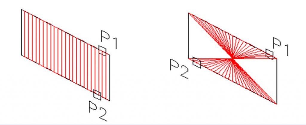
Picking Objects or Locations on the Drawing
To help you understand when an object or a location is picked, the modules use the letter ?P” along with a number that indicates which pick it is in the sequence. i.e.
(Do not attempt this Workalong now, it is here for an example only.)
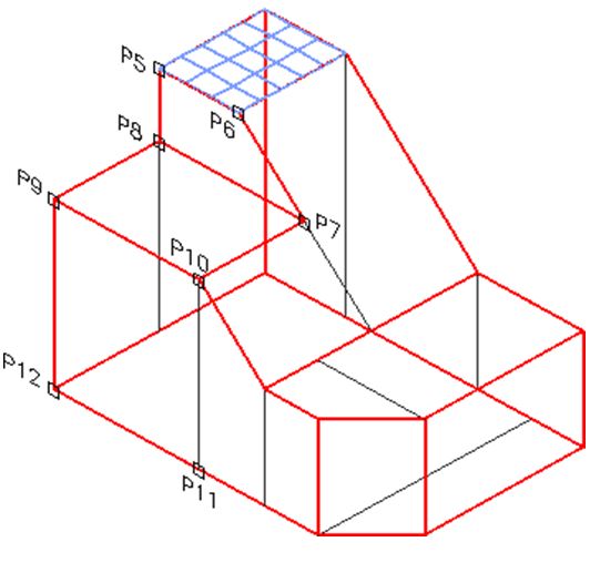
WORK ALONG: Using the 3DFACE and AI_MESH Commands
Step 15
Using the AI-MESH command shown below, insert two additional surfaces. See Figure Step 15A and 15B.
Command: AI_MESH
(Press F3 and enable Endpoint osnap mode. See Step 14.)
Specify first corner point of mesh: (end) P5
Specify second corner point of mesh: (end) P6
Specify third corner point of mesh: (end) P7
Specify fourth corner point of mesh: (end) P8
Enter mesh size in the M direction: 6
Enter mesh size in the N direction: 8
Command: AI_MESH
(Press F3 and enable Endpoint osnap mode. See Step 14.)
Specify first corner point of mesh: (end) P9
Specify second corner point of mesh:(end) P10
Specify third corner point of mesh: (end) P11
Specify fourth corner point of mesh: (end) P12
Enter mesh size in the M direction: 6
Enter mesh size in the N direction: 8
Command:
Author’s Comments
A comment by the author to help explain what is happening in a command is in italics inside brackets. For example:
Command: REVSURF
Current wire frame density: SURFTAB1=64 SURFTAB2=24
Select object to revolve
(Select the closed polyline.)
Select object that defines the axis of revolution:
(Select the axis line.)
Specify start angle <0>:
(Accept the default of 0.)
Specify included angle (+=ccw, -=cw) <360>:
(Accept the default.)
Command:
There are also author’s comments in the workalong or lab exercise to help you understand a principle or to complete a task. For example:
Key Principles
Key Principles in Module 1
- To complete the lab exercises in this book, you must have the four template files, that accompany it, on your hard disk drive.
- Do not skim through the Read and understand everything in each module. Do not jump around inside the module or from module to module. Work methodically through each module, page by page.
- The modules were written as competency-based bite-size pieces to allow you to work at your own pace and learn to use AutoCAD. Do not go onto the next module until you fully understood the module you are currently working on and have completed all lab
- All lab exercises have a time limit allocated to To complete a lab exercise in the specified time limit, you must be able to complete the drawing, check it for accuracy and make any corrections. If you cannot do this in the time allowed, redo the entire lab exercise. It is your way of proving that you mastered the module.
Do not memorized how to use AutoCAD – UNDERSTAND it.
Have fun on your journey into the fascinating world of mastering AutoCAD.
Using AutoCAD is a never ending learning process and you will continue learning long after completing this book
