Part 6
Module 27 Editing Solid Models – Part 1
Learning Outcomes
When you have completed this module, you will be able to:
- Describe how solid models are edited including the terms, body, face and edge.
- Apply the SOLIDEDIT command to edit faces of solid models.
Editing Solid Models
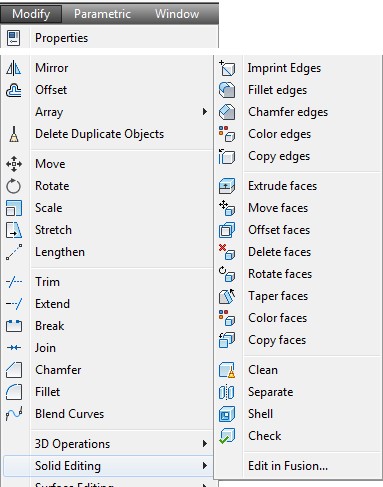
The SOLIDEDIT command is used to edit solid models. This powerful command has many options and is used to do most of the editing of existing solid models. When editing solids, you must be able to identify and select the body, faces and edges of the solid model.
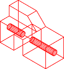
Body
A body is the solid model itself. See Figure 27-1.
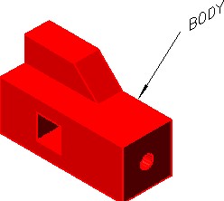
Body
Face
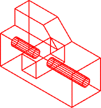
A face is the planer or curved 3D surfaces of the solid model. See Figure 27-2.
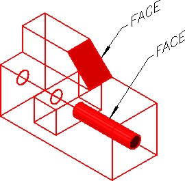
Faces
Edge
An edge is the shared object between two faces or surfaces of the solid. See Figure 27-3. Editing edges will be covered in Module 23.

Edges
AutoCAD Command: SOLIDEDIT
The SOLIDEDIT command is used to edit solid objects.
Shortcut: none

AUTHOR’S COMMENTS: One of the trickiest parts of using the SOLIDEDIT command is selecting the solid faces or edges that you want to edit. This command works differently than other commands when selecting objects. In all other commands, when the selected object is picked, at a ‘ select object ‘ prompt, only one object would be selected. In the SOLIDEDIT command, when an object is selected by picking it, more than one object is usually selected with one pick. The selected faces will highlight and then you have to remove the faces you do not want to edit. i.e.
Command: SOLIDEDIT
Solids editing automatic checking: SOLIDCHECK=1
Enter a solids editing option [Face/Edge/Body/Undo/eXit] <eXit>: _F
Enter a face editing option
[Extrude/Move/Rotate/Offset/Taper/Delete/Copy/coLor/Undo/eXit] <eXit>: E
Select faces or [Undo/Remove]: P1 2 faces found.
(In this example, 2 faces are selected with one pick.)
Select faces or [Undo/Remove/ALL]: R
Remove faces or [Undo/Add/ALL]: P2 2 faces found, 1 removed.
(One face is removed from the selection.)
Remove faces or [Undo/Add/ALL]:
WORK ALONG: Using the SOLIDEDIT Command
Step 1
Using the NEW command, start a new drawing using template: 3D Layout English.
Step 2
Save the drawing and name it: AutoCAD 3D Workalong 27-1.
Step 3
Draw the plines on layer: Pline and the solid model on layer: Solid 6.
Step 4
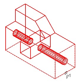
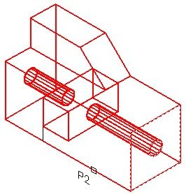
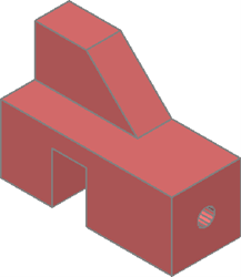
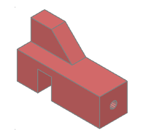
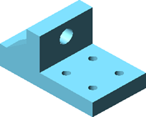
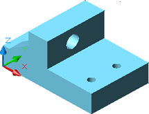
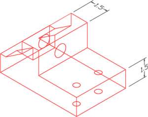
Draw a solid model of the object shown in the figures. (Figure Step 4A and 4B)
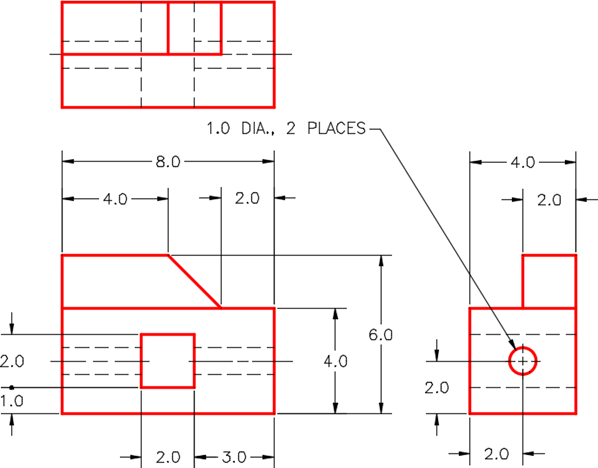
Dimensioned Multiview Drawing
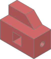
Solid Model
SE Isometric View
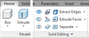
Step 5
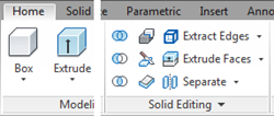
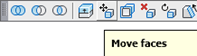
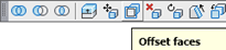
If you are using toolbars, enable the display of the Solids Editing toolbar. If you are using ribbons, use the Home tab. (Figure Step 5)
Step 6
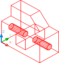
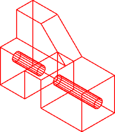
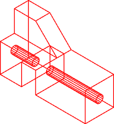
Set the view to SE Isometric, the current visual style to 3D Wireframe and the UCS in World. (Figure Step 6)
Step 7
Click the Extrude Faces icon and, as shown below, to extrude the face on the right. (Figure Step 7A, 7B, and 7C)
Command: SOLIDEDIT
Solids editing automatic checking: SOLIDCHECK=1
Enter a solids editing option [Face/Edge/Body/Undo/eXit] <eXit>: F
Enter a face editing option
[Extrude/Move/Rotate/Offset/Taper/Delete/Copy/coLor/Undo/eXit] <eXit>: E
Select faces or [Undo/Remove]: P1 2 faces found.
(Select the face. Notice it finds 2 faces.)
Select faces or [Undo/Remove/ALL]: R
(Remove one of the faces.)
Remove faces or [Undo/Add/ALL]: P2 2 faces found, 1 removed.
Remove faces or [Undo/Add/ALL]:
Specify height of extrusion or [Path]: 2
(Extrude the face 2 units in the positive direction.)
Specify angle of taper for extrusion <0>:
Solid validation started.
Solid validation completed.
Command:
Step 8
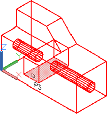
Click the Extrude Faces icon and complete the command, as shown below, to extrude the face to the bottom. (Figure Step 8A and 8B)
Command: SOLIDEDIT
Solids editing automatic checking: SOLIDCHECK=1
Enter a solids editing option [Face/Edge/Body/Undo/eXit] <eXit>: F
Enter a face editing option
[Extrude/Move/Rotate/Offset/Taper/Delete/Copy/coLor/mAterial/Undo/eXit] <eXit>: E
Select faces or [Undo/Remove]: P3 1 face found.
Select faces or [Undo/Remove/ALL]:
Specify height of extrusion or [Path]: -1
Specify angle of taper for extrusion <0>:
Solid validation started.
Solid validation completed.
Enter a face editing option
[Extrude/Move/Rotate/Offset/Taper/Delete/Copy/coLor/mAterial/Undo/eXit] <eXit>:
Command:
Step 9
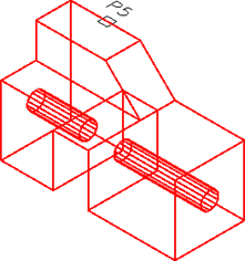
Click the Move Faces icon and complete the command shown below to move the face on the top of the model higher. (Figure Step 9A, 9B, 9C, and 9D)
Command: SOLIDEDIT
Solids editing automatic checking: SOLIDCHECK=1
Enter a solids editing option [Face/Edge/Body/Undo/eXit] <eXit>: F
Enter a face editing option
[Extrude/Move/Rotate/Offset/Taper/Delete/Copy/coLor/Undo/eXit] <eXit>: M
Select faces or [Undo/Remove]: P5 2 faces found.
Select faces or [Undo/Remove/ALL]: R
Remove faces or [Undo/Add/ALL]: 2 faces found, 1 removed.
Remove faces or [Undo/Add/ALL]:
Specify a base point or displacement: 0,0,0
Specify a second point of displacement: @0,0,1
(Move the in the positive Z or up 1 unit.)
Solid validation started. Solid validation completed.
Enter a face editing option
Command:
Step 10
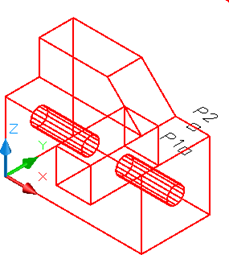
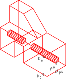
Click the Offset Faces icon and complete the command, as shown below, to offset the face and the hole onthe right side 2 inches longer.(Figure Step 10A, 10B, 10C, and 10D)
Command: SOLIDEDIT
Solids editing automatic checking: SOLIDCHECK=1
Enter a solids editing option [Face/Edge/Body/Undo/eXit] <eXit>: F
Enter a face editing option
[Extrude/Move/Rotate/Offset/Taper/Delete/Copy/coLor/Undo/eXit] <eXit>: O
Select faces or [Undo/Remove]: P6 2 faces found.
Select faces or [Undo/Remove/ALL]: R
Remove faces or [Undo/Add/ALL]: P7 2 faces found, 1 removed.
Remove faces or [Undo/Add/ALL]: A
(This time a face must be added in.)
Select faces or [Undo/Remove/ALL]: P8 2 faces found. Select faces or [Undo/Remove/ALL]: R
Remove faces or [Undo/Add/ALL]: P9 1 face found, 1 removed.
Remove faces or [Undo/Add/ALL]:
Specify the offset distance: 2
(Offset distance is 2 units.)
Solid validation started.
Solid validation completed.
Enter a face editing option
Command:
Step 11
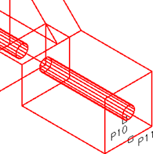
Click the Delete Faces icon and complete the command shown below to delete a the hole in the model. (Figure Step 11A, 11B, and 11C)
Command: SOLIDEDIT
Solids editing automatic checking: SOLIDCHECK=1
Enter a solids editing option [Face/Edge/Body/Undo/eXit]
<eXit>: F
Enter a face editing option
[Extrude/Move/Rotate/Offset/Taper/Delete/Copy/coLor/Undo/ eXit] <eXit>: D
Select faces or [Undo/Remove]: P10 2 faces found.
Select faces or [Undo/Remove/ALL]: R
Remove faces or [Undo/Add/ALL]: P11 2 faces found, 1 removed.
(Remove the left face and keep the hole face.)
Remove faces or [Undo/Add/ALL]:
Solid validation started.
Solid validation completed.
Enter a face editing option
Command:
Step 12
Save and close the drawing.
Key Principles
Key Principles in Module 27
- When editing solids, you must be able to identify and select the body, faces and edges of the solid model.
- When editing solids, always use the Solids Editing toolbar instead of trying to enter the commands using another method.
- One of the trickiest parts of using the SOLIDEDIT command is selecting the solid faces or edges that you want to edit.
Lab Exercise 27-1
Time allowed: 30 minutes.
| Drawing Name | Template | Units |
|---|---|---|
| AutoCAD 3D Lab 27-1 | N/A | Inches |
Step 1
Open the drawing: AutoCAD 3D Lab 18-5 and save it with the name: AutoCAD 3D Lab 27-1.
Step 2
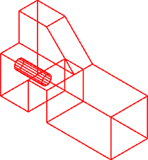
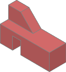
Using the SOLIDEDIT command only, edit the solid to appear as shown in the figures. (Figure Step 2A, 2B, and 2C)

Solid Before
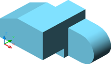
Completed Solid Model
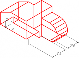
Dimensioned Model
Lab Exercise 27-2
Time allowed: 30 minutes.
| Drawing Name | Template | Units |
|---|---|---|
| AutoCAD 3D Lab 27-2 | N/A | Inches |
Step 1
Open the drawing: AutoCAD 3D Lab 17-1 and save it with the name: AutoCAD 3D Lab 27-2
Step 2
Using the SOLIDEDIT command only, edit the solid to appear as in the figures. (Figure Step 2A, 2B, and 2C)
Solid Before
Completed Solid Model
Dimensioned Model
