Part 6
Module 30 Creating 2D Drawings from Solid Models
Learning Outcomes
When you have completed this module, you will be able to:
- Apply the SOLVIEW, SOLDRAW, and SOLPROF commands to automatically create 2D working multiview drawings, including pictorial views, from solid models.
Creating 2D Drawings from Solid Models
After an object is constructed as a solid 3D model, there are AutoCAD commands and features available to create and dimension a 2D working multiview drawing. Before you go any farther in this module, you must know and understand the following concepts:
- Creating and modifying AutoCAD layout drawings.
- Working in paper space.
- Creating, editing and setting the scale of viewports.
These three concepts are covered in the AutoCAD 2D book.
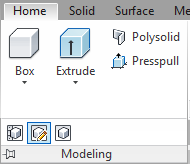
AutoCAD Command: SOLVIEW
The SOLVIEW command is used to create views and the necessary layers of a 3D solid model.
Shortcut: none

Important: Before you use the SOLVIEW command, ensure that the current visual style is 2D Wireframe and the Hidden linetype is loaded into the drawing.
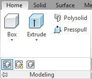
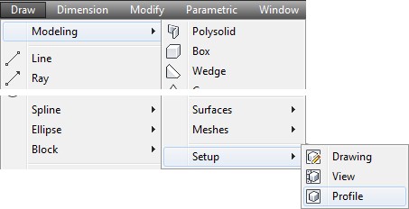
AutoCAD Command: SOLPROF
The SOLPROF command is used to create a profile of edges of straight and curved surfaces of a solid model as it is viewed from a selected viewpoint.
Shortcut: none
Important: Before you use the SOLPROF command, ensure that the current visual style is 2D Wireframe and the Hidden linetype is loaded into the drawing.
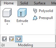
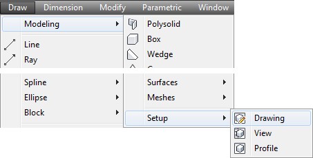
AutoCAD Command: SOLDRAW
The SOLDRAW command is used to convert views created by the SOLVIEW command by projecting the 3D objects onto a 2D plane and changing hidden objects onto the hidden layer.
Shortcut: none
WORK ALONG: Creating 2D Drawings from a Solid Model
Step 1
Using the NEW command, start a new drawing using template: 3D Layout English.
Step 2
Save and name the drawing: AutoCAD 3D Workalong 30-1.
Step 3
Set the current UCS as World, the current view as SE Isometric, and the current visual style to 2D Wireframe.
Step 4
Using the LINETYPE command, ensure that the Hidden linetype is loaded in the current drawing.
Step 5
Set the Insertion Units to inches and insert the block: AutoCAD 3D Workalong 30-1 at 0,0,0.
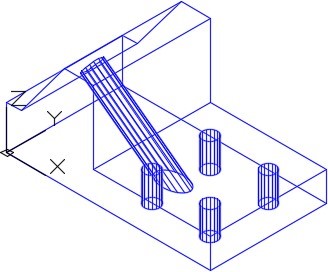
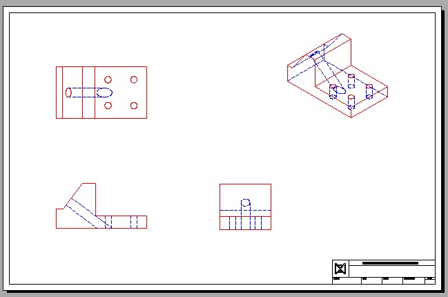
Step 6
Explode the block and change the layer that the solid model is on to layer: Solid 7. Using the Properties window, check to ensure that the object is a 3D solid. (Figure Step 6)
Step 7
Save the drawing but do not close it.
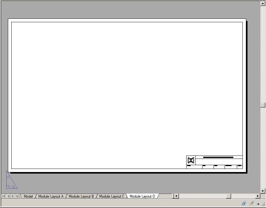
Step 8
Enable layout: Module Layout D. (Figure Step 8)
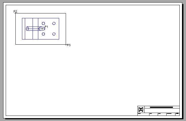
Step 9
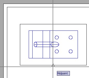
Enter the SOLVIEW command, as shown below, to create the top view of the model. Name it: Top. (Figure Step 9)
Command: SOLVIEW
Enter an option [Ucs/Ortho/Auxiliary/Section]: U
(Enter U to draw the view from the UCS.)
Enter an option [Named/World/?/Current] <Current>:
(Accept the default Current.)
Enter view scale <1.0000>:
(Accept the scale of 1.)
Specify view center: P1
(Select a location for the centre of the view.)
Specify view centre <specify viewport>:
(Press Enter to accept the location.)
Specify first corner of viewport: P2
Specify opposite corner of viewport: P3
Enter view name: Top
(The view must be named.)
Command:
Step 10
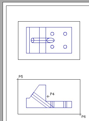
Enter the SOLVIEW command again, but this time create the front view by projecting orthographically from the top view. Name it: Front. When done that way, the two views will be aligned. (Figure Step 10A and 10B)
Command: SOLVIEW
Enter an option [Ucs/Ortho/Auxiliary/Section]: O
Specify side of viewport to project: (mid)
Specify view center: P4
Specify view centre <specify viewport>:
Specify first corner of viewport: P5
Specify opposite corner of viewport: P6
Enter view name: Front
Command:
Step 11
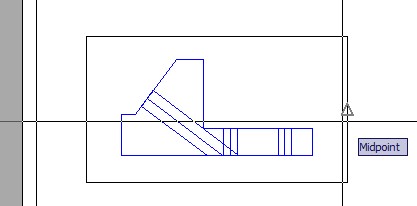
Using what you just learned, create the right side view and name it: Right. (Figure Step 11A and 11B)
Command: SOLVIEW
Enter an option [Ucs/Ortho/Auxiliary/Section]: O
Specify side of viewport to project:(mid)
Specify view center:
Specify view centre <specify viewport>:
Specify first corner of viewport:
Specify opposite corner of viewport:
Enter view name: Right
Enter an option [Ucs/Ortho/Auxiliary/Section]:
Command:
Step 12
Use the MVIEW command to create a viewport in the top right corner of the drawing. Change the scale of the viewport to 1:1 and the current view to SE Isometric. Pan the model in the viewport to centre it. (Figure Step 12)

Step 13
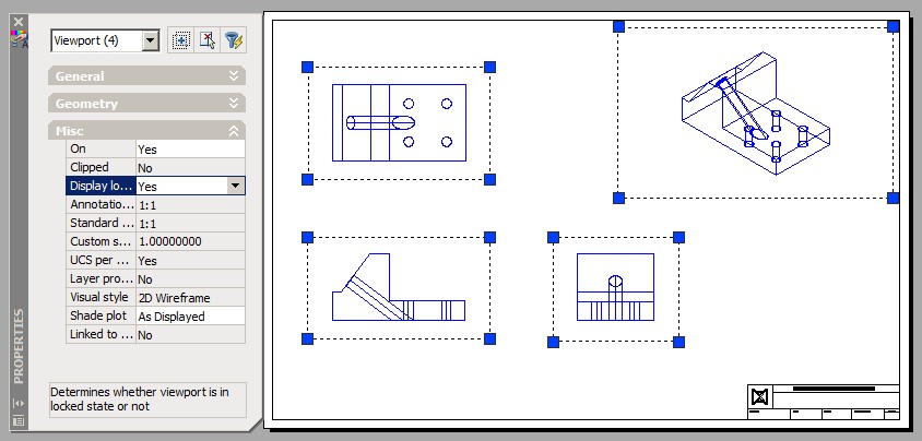
Using the UNITS command, set the length precision to 8 decimal places. Open the Properties window and select all four viewports as shown in the figure. Check to ensure that the scale of all viewports are set to 1:1. Lock their display. (Figure Step 13)
Step 14
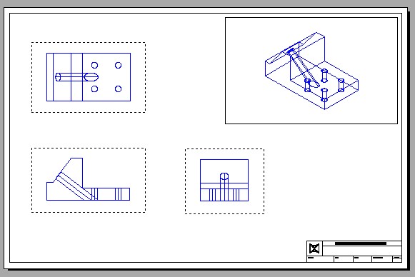
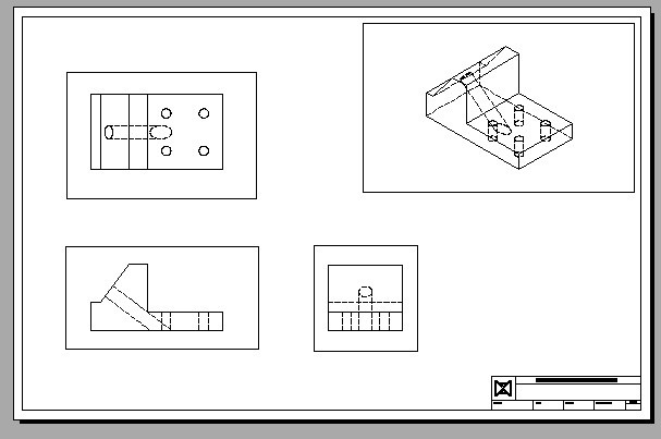
Enter the SOLDRAW command, as shown below, to change the multiviews viewports to 2D. (Figure Step 14A and 14B)
Command: SOLDRAW
Select viewports to draw.
Select objects: 1 found
Select objects: 1 found, 2 total
Select objects: 1 found, 3 total
(Select the three multiview viewports.)
Select objects:
One solid selected.
One solid selected.
One solid selected.
Command:
Step 15
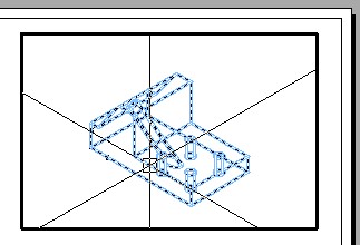
Change to current space to Model and select the isometric view as the current viewport. Enter the SOLPROF command as shown below. (Figure Step 15A and 15B)
Command: SOLPROF
Select objects: 1 found
(Select the solid model.)
Select objects:
Display hidden profile lines on separate layer? [Yes/No] <Y>:
(Select the default.)
Project profile lines onto a plane? [Yes/No] <Y>:
(Select the default.)
Delete tangential edges? [Yes/No] <Y>:
(Select the default.)
Enter an option
Command:
Step 16
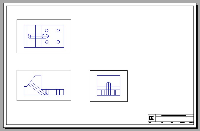
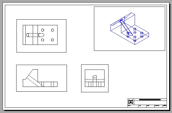
Change the colors of the layers as shown in the figure. (Figure Step 16)
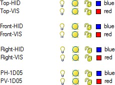
Step 17
Turn Layer: VPORT off and your completed drawing should appear similar to the figure. (Figure Step 17)
Step 18
Save and close the drawing.
Key Principles
Key Principles in Module 30
- Before you use the SOLVIEW and the SOLPROF commands, ensure that the current visual style is 2D Wireframe and the Hidden linetype is loaded into the current drawing.
Lab Exercise 30-1
Time allowed: 45 minutes.
| Drawing Name | Template | Units |
|---|---|---|
| AutoCAD 3D Lab 30-1 | 3D English Layout | Inches |
Step 1
Start a new drawing using the template shown above.
Step 2
Draw the plines on layer: Pline and the solid model on layer: Solid 3.
Step 3
Using the figures as a reference, draw the solid model. (Figure Step 3A, 3B, and 3C)
The Solid Model – SE Isometric View
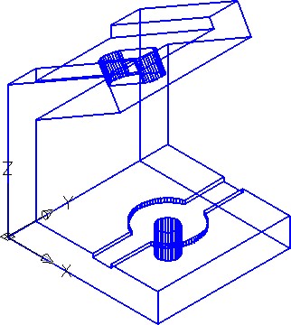
Visual Style – 2D Wireframe
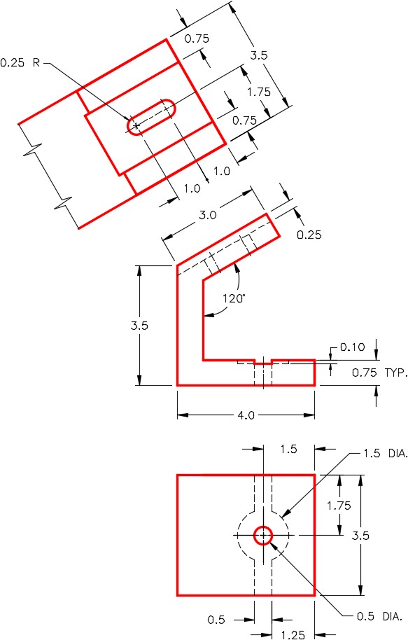
Dimensioned Multiview Drawing
Step 4
Enable layout: Module Layout D and using the command SOLVIEW, create the three multiviews. Set the scale of the viewports to 1.5:1 and lock their display.
Step 5
Use the SOLDRAW command to change the views to 2D.
Step 6
Using the MVIEW command, create two views and set their view to SE Isometric. Scale the viewports to 1:1 and lock their display. Set one of the views to display shaded.
Step 7
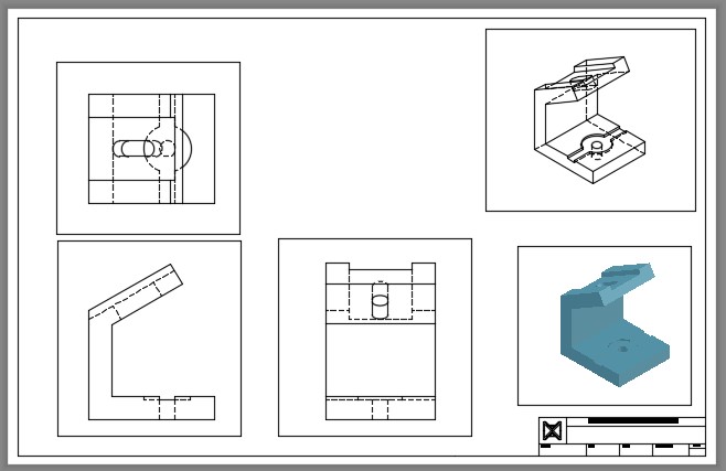
Use the SOLPROF command to create the hidden lines in the isometric viewport. (Figure Step 7)
Step 8
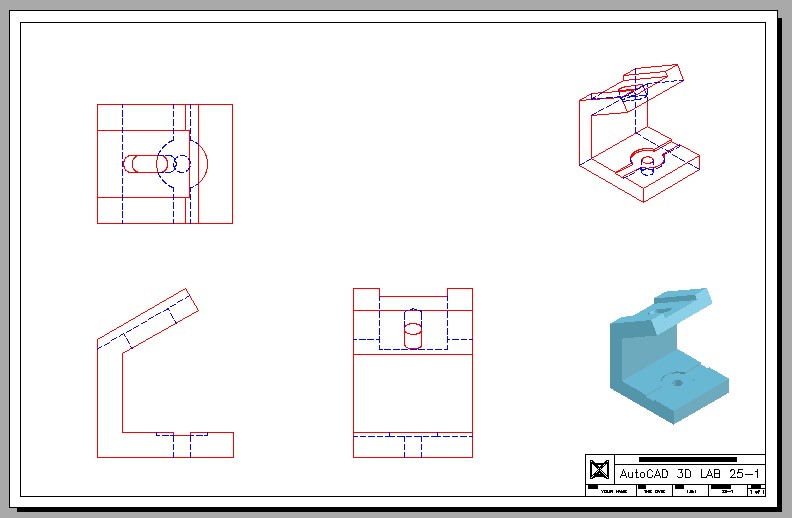
Change the color of the layers to Red for object lines and Blue for the hidden lines. (Hint: See Step 16 of WORKALONG: Creating 2D Drawings from a Solid Model)
Step 9
Fill in the titleblock in paper space.
Step 10
Turn layer: VPORT off. (Figure Step 10)
Step 11
Save and close the drawing.
