Part 1
Module 1: Viewing 3D Models – Part 1
Learning Outcomes
When you have completed this module, you will be able to:
- Describe AutoCAD’s Ribbon and Toolbar menu systems and set one to used for this book.
- Describe a wireframe model and explain how it is viewed in 3D.
- Describe the UCS icon and explain how to configure and display it.
- Apply the VIEW, 3DORBIT, 3DFORBIT, 3DCORBIT, and UCSICON commands.
AutoCAD’s Menu Systems
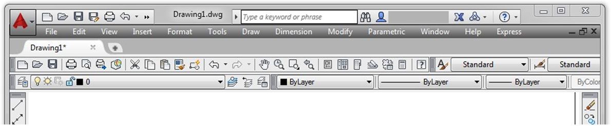
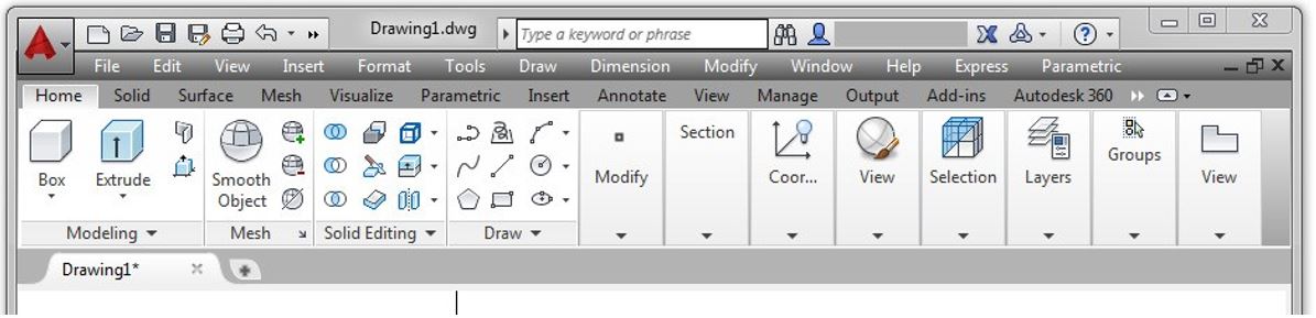
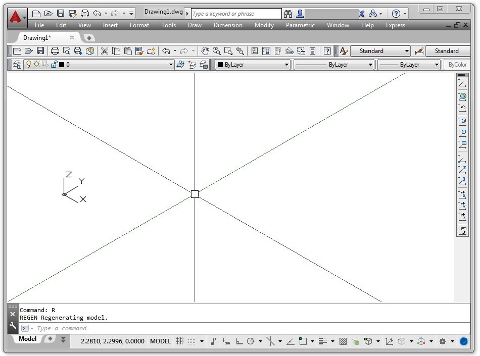
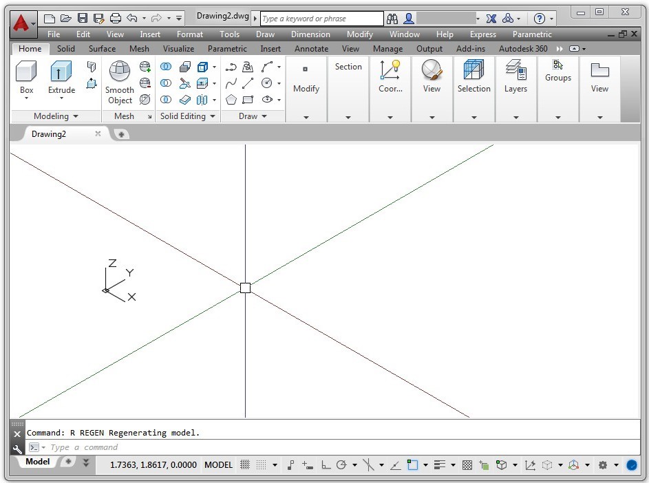
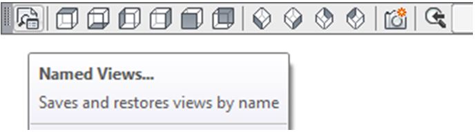
AutoCAD has two menu systems that allows you to communicate with it. The two menu systems are Toolbar menu and Ribbon menu. See Figure 1-1. You can, and should, add the Pull-down menu to either the Toolbar or the Ribbon menu. You can use either menu system when completing labs exercises in this book. You can switch between them, if you wish.
WORK ALONG: Setting AutoCAD’s Interface Using Toolbar Menus
If you are using Ribbon menus, skip to WORK ALONG: Setting AutoCAD’s Interface Using Ribbon Menus
Step 1
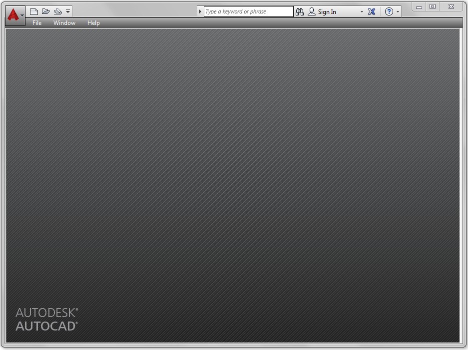
Launch AutoCAD. AutoCAD’s blank window will display. (Figure Step 1)

Step 2
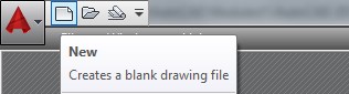
Click the New icon. This will open the Select Template dialogue box. (Figure Step 2)
Step 3
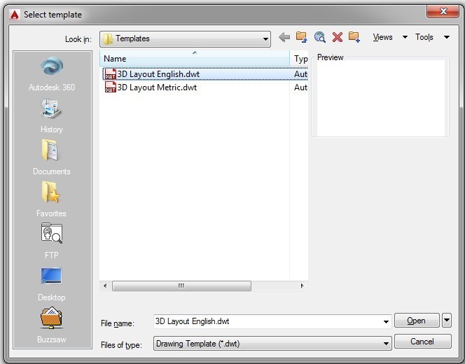
In the Select template dialogue box, click the template file: 3D Layout English to highlight it. Then click the Open button. This will open AutoCAD’s Graphic window. (Figure Step 3)
Step 4
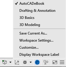
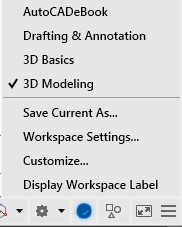
Click the small arrow in the Workplace Switching icon on the Status bar. Click the workspace: AutoCADbook to set it as the current workspace. Make sure that the check mark is beside the workspace: AutoCADbook as shown in the figure. (Figure Step 4A and 4B)
Step 5
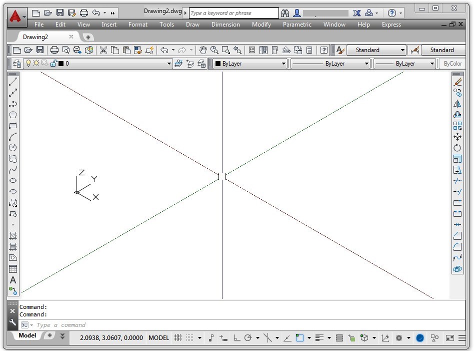
Check to ensure that the tab Model is enabled. It is located on the bottom left corner of the Graphic window. If it is not enabled, click it with the left mouse button. (Figure Step 5)

Step 6
Disable all features on the Status bar by clicking any that display with a blue background as shown in Figure Step 6A. All features should display with a gray background as shown in Figure Step 6B. (Figure Step 6A and 6B)


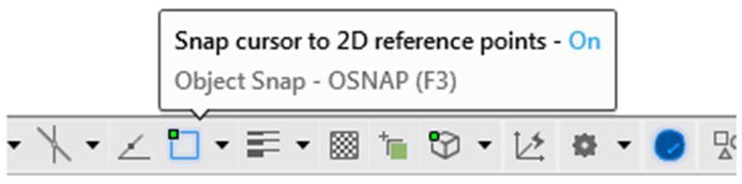
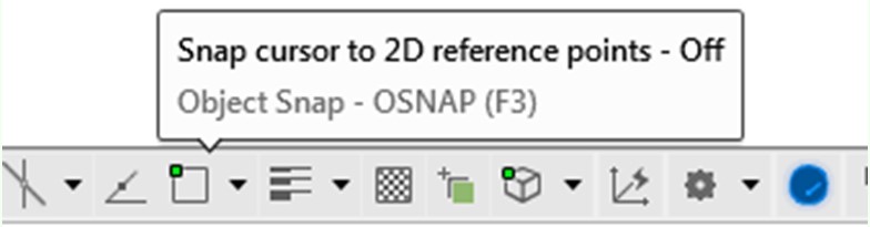
USER TIP: You can easily check to see if a feature on the Status bar is enabled or disabled by holding your graphic cursor on the icon. A pop up window will display indicating the name of the feature and whether it is currently on or off as shown in the figures below.

Step 7
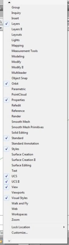
Move the Graphic cursor onto any toolbar icon and right click the mouse. This will pull down a list of all available toolbar menus. The ones that are preceded with a checkmark are enabled and are currently displayed in the Graphic window. Ensure that the toolbars: Layers, Orbit, Properties, Standard, Styles, UCS, UCS II, View, and Visual Styles are the only ones enabled. Click on the name to toggle the display of the toolbar. (Figure Step 7)
Step 8
Your Graphic screen should match the figure very closely. (Figure Step 8)
Step 9
Enter the MENUBAR command. If is set to 0, set it to 1, as shown below.
Command: MENUBAR
Enter new value for MENUBAR <0>: 1
Command:
Step 10
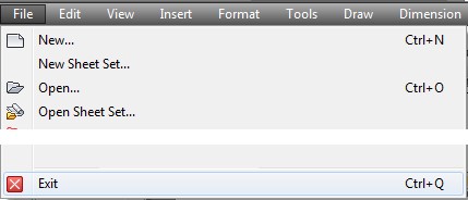
Click File on the Pull-down menu. Click Exit to close AutoCAD. If you are asked if you want to save the drawing, click No. (Figure Step 10)

Step 11
Skip to Viewing in 3D
WORK ALONG: Setting AutoCAD’s Interface Using Ribbon Menus
If you are using Toolbar menus, go to Viewing in 3D
Step 1
Launch AutoCAD. AutoCAD’s blank window will display. (Figure Step 1)
Step 2
Click the New icon. This will open the Select Template dialogue box. (Figure Step 2)

Step 3
In the Select Template dialogue box, click the template file: 3D Layout English to highlight it. Then click the Open button. This will open AutoCAD’s Graphic window. (Figure Step 3)

Step 4
Click the small arrow in the Workplace Switching icon on the Status bar. Click the workspace: 3D Modeling to set it as the current workspace. Ensure that the check mark is beside the workspace: 3D Modeling as shown in the figure. (Figure Step 4A and 4B)
Step 5
Enter the MENUBAR command and if is set to 0, set it to 1, as shown below. Command: MENUBAR
Enter new value for MENUBAR <0>: 1
Command:
Step 6
Check to ensure that the tab Model is enabled. If it is not enabled, click it with the left mouse button. (Figure Step 6)

Step 7
Disable all features on the Status bar by clicking any that display with a blue background as shown in Figure Step 7A. All features should display with a gray background as shown in Figure Step 7B. (Figure Step 7A and 7B)


Step 8
Click File on the Pull-down menu. Click Exit to close AutoCAD. If you are asked if you want to save the drawing, click No. (Figure Step 8)
USER TIP: You can easily check to see if a feature on the Status bar is enabled or disabled by holding yourgraphic cursor on the icon. A pop up window will display indicating the name of the feature and whether it is currently on or off as shown in the figures on the right.
Viewing in 3D
While working in 2D (two dimensions), the model was always viewed looking down from the top. The only viewing adjustment made, when looking at the model, was the distance (zoom) and the location (pan). There was no need to change the viewing angle. Working in 3D (three dimensions) is quite different. While the model can still be zoomed and panned, you can change the viewing direction and angle of the model.
Throughout the AutoCAD 2D book, the objects being drawn and modified were called the drawing objects even though they were actually model objects on the top view of a model. The reason this was done was to keep it simple and allow you to concentrate on learning to draw and modify geometry. In the AutoCAD 3D book, all objects that are drawn in model space will be referred to as model objects and all objects drawn in paper space will be called drawing objects.
UCS Icon
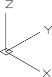
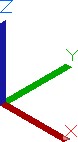
The User Coordinate System (UCS) icon displays the location and orientation of the current coordinate system. Its location, which is controlled by you, is at either the current coordinate system origin point or in the lower-left corner of the current viewport. When constructing a model, it is best to locate it at the origin point as taught in Modules 3 and 4. Figure 1-2 shows the two different icons as they would appear in a 3D viewing orientation.
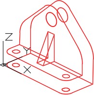
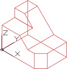
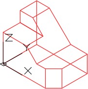
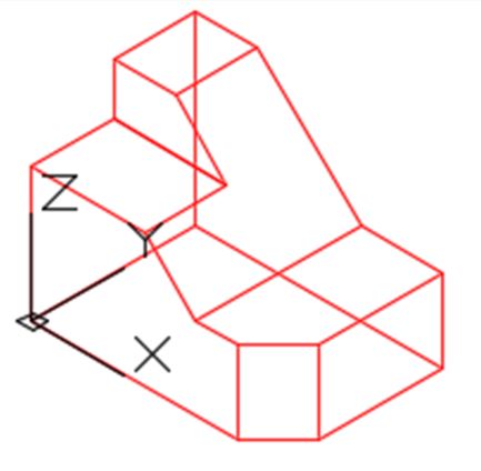
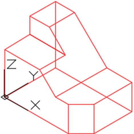
A Wireframe Model
A model is the 3 dimensional object drawn at full size and located accurately in relation to model space origin or X0Y0Z0 in the World UCS. A wireframe model is a real-world 3D object represented by lines, circles, arcs, and/or plines located along the edge of the model. See Figure 1-3. A wireframe model is hollow in the centre. That is the reason that lines and arcs on the opposite side of the model can be seen. Think of it as the skeleton of an object. The same model when surfaced or constructed as a solid model will appear as shown in Figure 1-4.
Surfacing a wireframe model and constructing a solid model are covered in Modules 12 to 30.
Wireframe models can be used to view the model from any vantage point, generate standard views in a drawing, generate exploded and perspective views, plus can be used as a skeleton when constructing the surfaced model. A wireframe model cannot be shaded or rendered. A wireframe model can also be used to analyze spatial relationships, including the shortest distance between corners and edges and checking for interferences.
It is important to plan, organize, and construct your model using layers and colors. This will allow you to more easily visualize a complex model and differentiate between objects in various views.
Wireframe Model
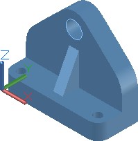
A Surfaced or Solid Model
A View
A view is an area displayed by the viewing angle and direction and the location of the target. The current view is the view of the model that is being displayed in the Graphic window. There are many ways of setting the current view of the model and all of them will be covered throughout the AutoCAD 3D book. In this module, using the VIEW command is taught to either select a preset view or set and name user defined views. The basic principles of the orbit commands are also covered.
AutoCAD Command: VIEW
The VIEW command is used to display the preset views or to define, name, and display user defined views of the model.
Shortcut: none

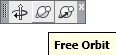
AutoCAD Commands: 3DORBIT, 3DFORBIT, 3DCORBIT
The 3DORBIT, 3DFORBIT, and 3DCORBIT commands allows the user to dynamically orbit the
model changing the viewing angle, viewing direction, and target of the view.
Shortcut: none
AutoCAD Commands: UCSICON
The UCSICON command is used to configure and control the display of the UCS icon.
Shortcut: none
WORK ALONG: Using the UCSICON, VIEW, and 3DFORBIT Commands
Step 1
Using the NEW command, start a new drawing using the template: 3D Layout English.
Step 2
Save and name the drawing: AutoCAD 3D Workalong 01-1.
Step 3
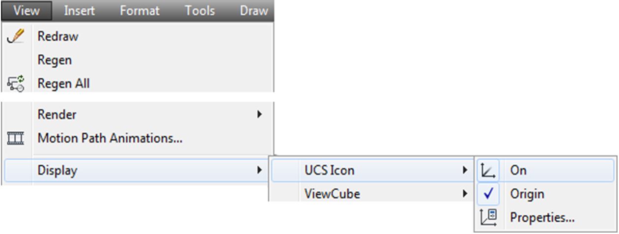
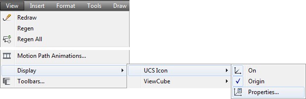
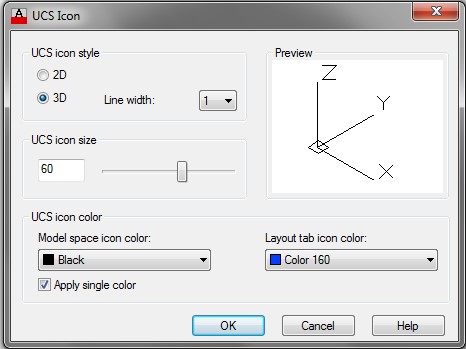
In the View pull-down, select Display – UCS Icon – Properties. Ensure that both On and Origin enabled as shown in the figure. This will open the UCS Icon dialogue box. Ensure that the settings are the same in your dialogue box as they are in the figure. (Figure Step 3A and 3B)
Step 4
Enter the UNITS command. In the Units dialogue box, set the Insertion Units to Inches. Using the INSERT command, insert the block: AutoCAD 3D Lab 01-1 at the coordinates 0,0,0. Explode the block that you just inserted. Your model should appear as shown in the figure. (Figure Step 4)
Step 5
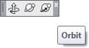
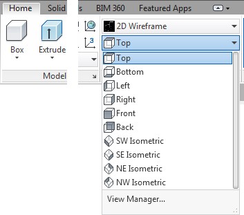
If you are using Toolbar menus, use the View toolbar or if you are using Ribbon menus, use the View section of the Home tab to complete Steps 7 and 8. (Figure Step 5A and 5B)

Step 6
Enter the system variable UCSORTHO, as shown below, and set it to 0.
Command: UCSORTHO
Enter new value for UCSORTHO <1>: 0
Command:
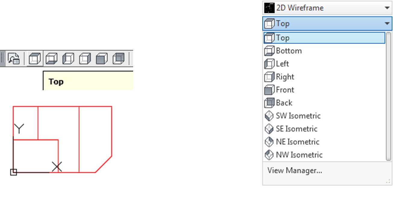
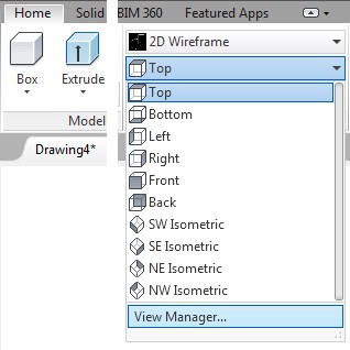
Step 7
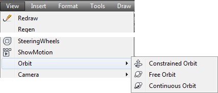
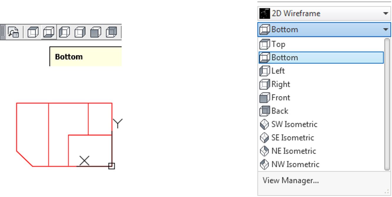
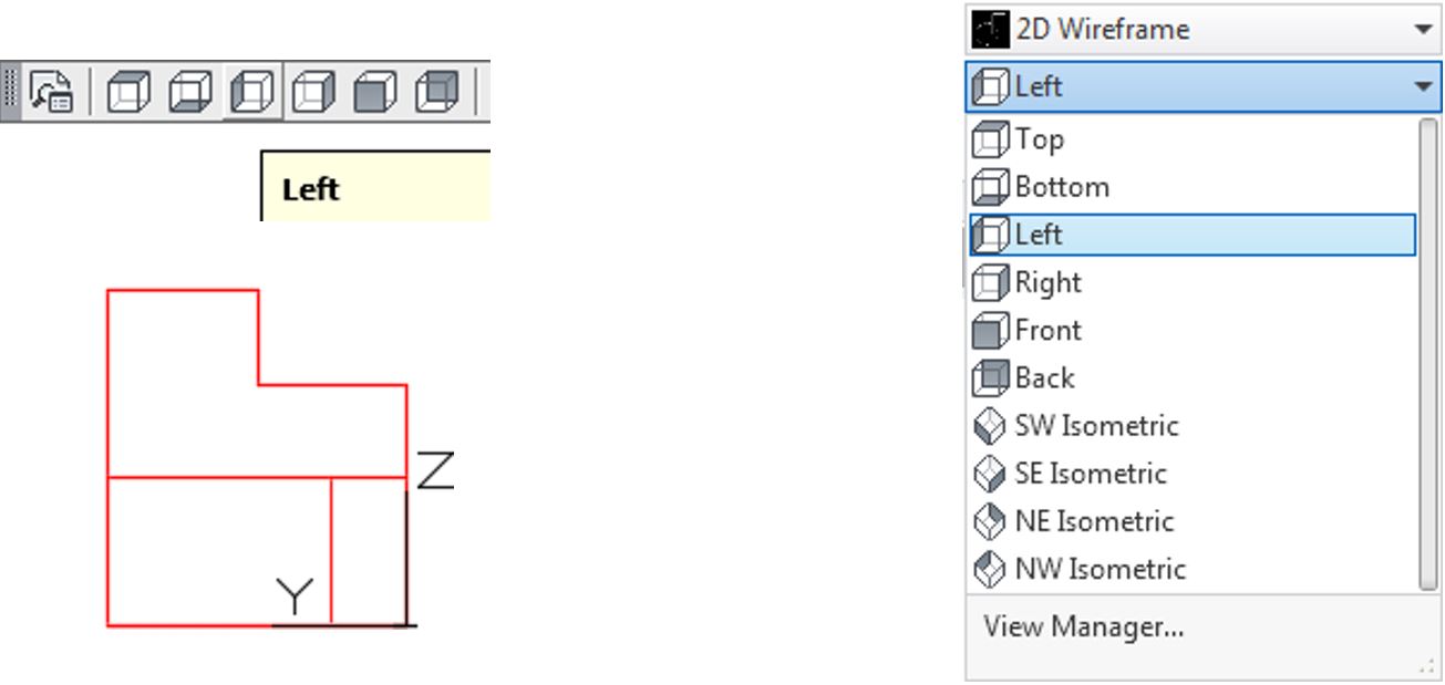
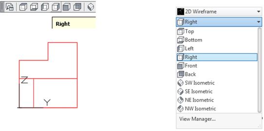
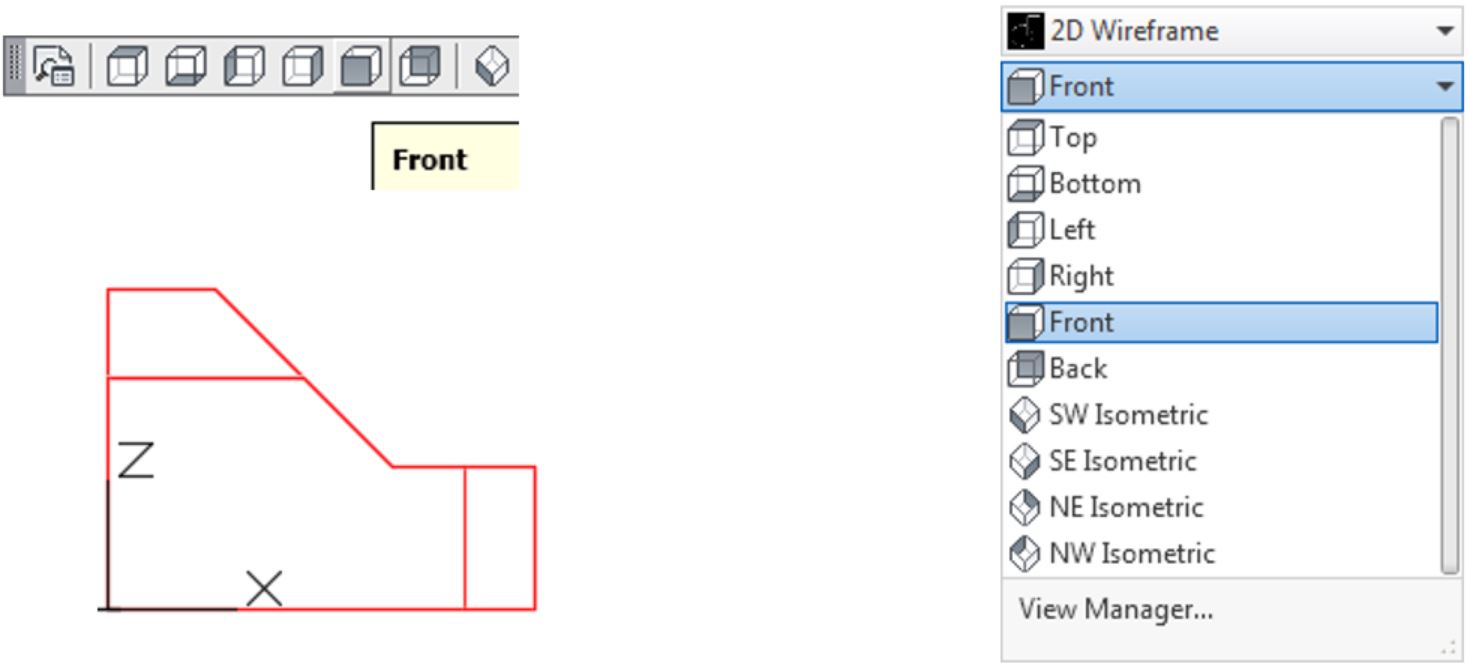
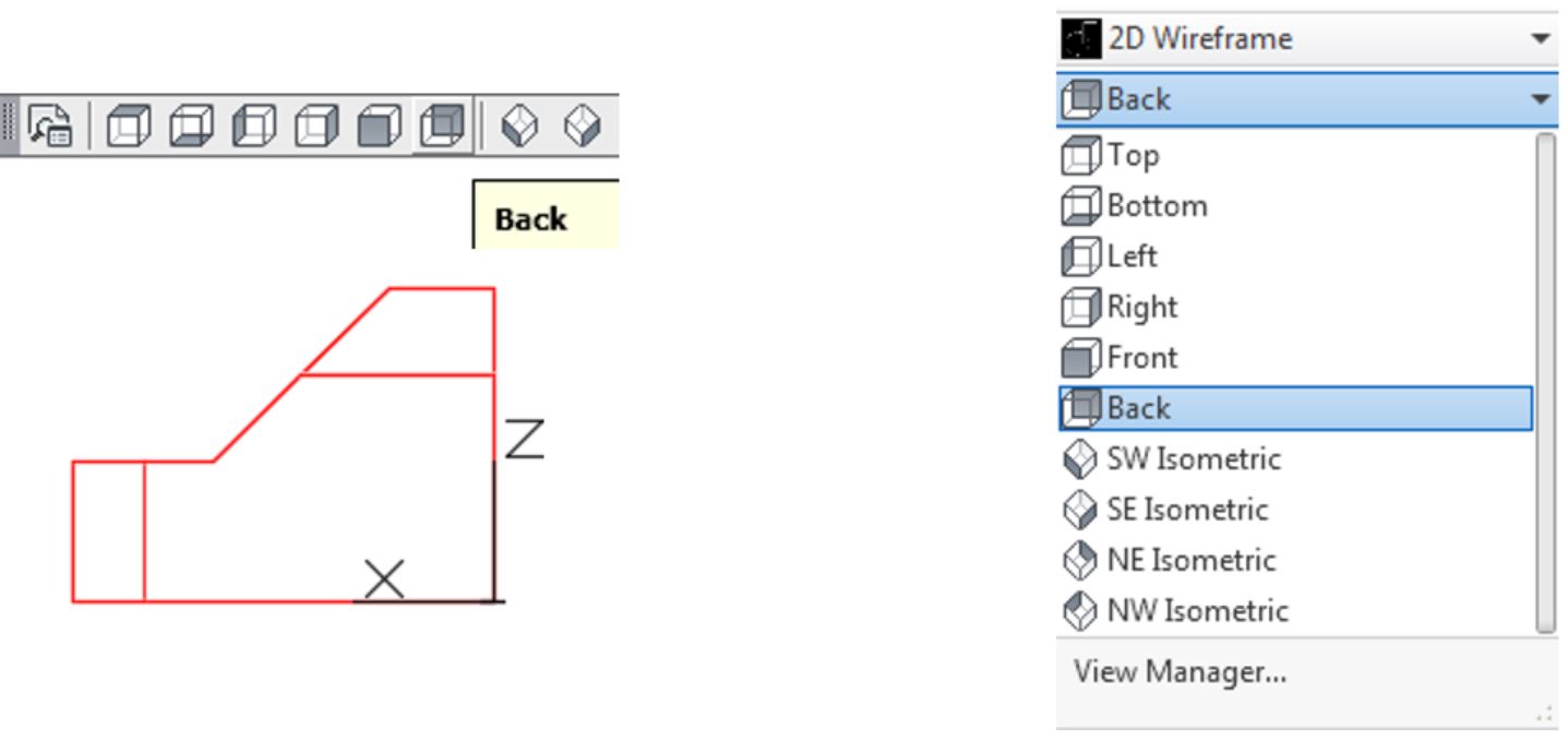
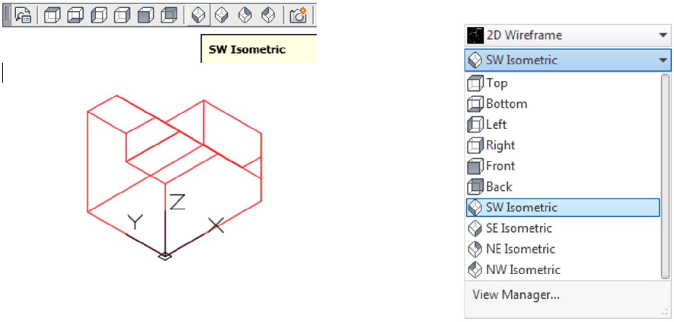
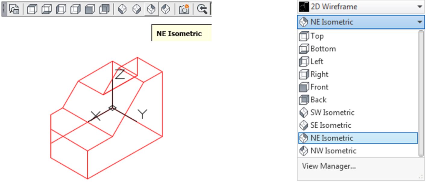
Click the Top view icon. Note how the model is now being viewed from the top as shown in the figure. Continue to change the view to display the ten predefined views. Note how the view of the model changes each time you click an icon. (Figure Step 7A, 7B, 7C, 7D, 7E, 7F, 7G, 7H, 7I, and 7J)
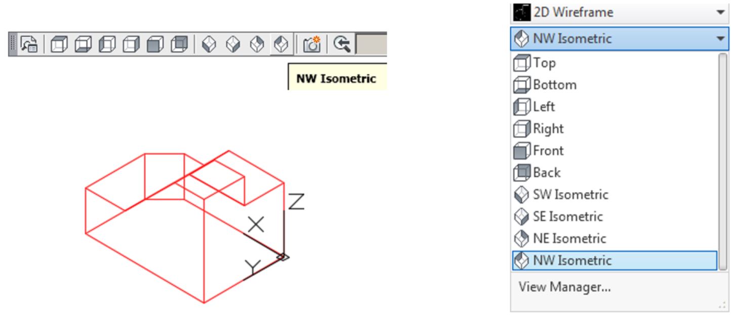
Step 8
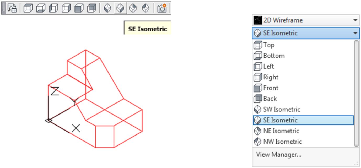
Change the current view to SE Isometric as shown in the figure. (Figure Step 8)

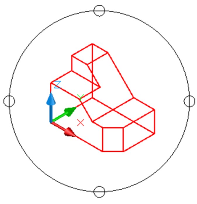
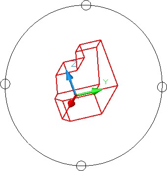
AUTHOR’S COMMENTS: The 3DFORBIT command activates and displays the arcball. The arcball allows you to dynamically orbit the model changing the viewing angle, viewing direction and target. The arcball displays a small circle at each quadrant. See Figure 1-5
Depending on the location of the cursor when the left mouse button is held down, the model will orbit around a different axis. If the cursor is located:
- outside the arcball the Z
- on the upper or lower circles the X
- on the left or right circles, the Y axis
- inside the arcball, the XYZ
In this module, only the basic principles of the 3DFORBIT command are covered. Play with this command and practice orbiting the model around each of the axis. After entering the command, move the cursor to the desired location press and hold down the left mouse button and move the cursor. Press Esc to exit the command. Any change can be reversed with the U command.
Be careful when orbiting the model. It is very easy to over-orbit it and lose your mental view of the model. Orbit it slowly and deliberately keeping a mental view of the model throughout. If you lose the mental view of the model, you can always exit the orbit and change the view to SE Isometric and then start the orbit again. The 3DFORBIT command will be covered in greater detail as you work your way through the AutoCAD 3D book.
The Arcball
Step 9
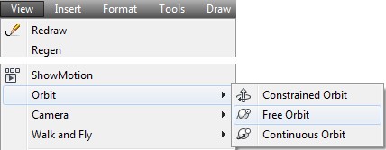
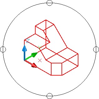
Enter the 3DFORBIT command using either the toolbar or the pull-down menu. It will display the arcball around the model. Zoom and pan the model to locate it in the centre of the arcball. (Figure Step 9A, 9B, and 9C)
Step 10
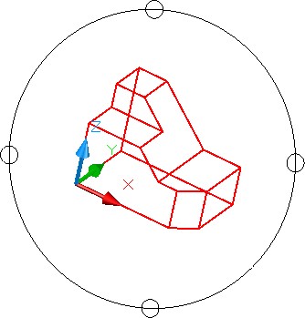
Move the cursor onto the small circle on the left side. Press and hold down the left mouse button and while holding it down, move the cursor slowly to the right. until your model appears similar to the figure. You do not have to move it very far. (Figure Step 10)
Step 11
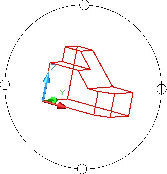
Move the cursor onto the small circle on the bottom. Press and hold down the left mouse button and while holding it down, move the slowly up until your model appears as shown in the figure. (Figure Step 11)
Step 12
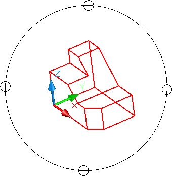
Move the cursor inside the arcball. Press and hold down the left mouse button and while holding it down, move it until the model appears as shown in the figure. (Figure Step 12)
Step 13
Press Esc to exit the command. Change the current view to SE Isometric. (Figure Step 13)
Step 14
Using 3DFORBIT, orbit the model to appear similar to the figure. It does not have to match exactly. (Figure Step 14)
Step 15
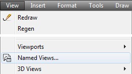
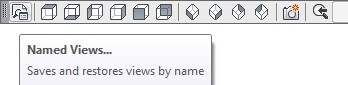
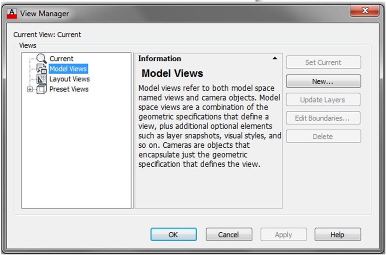
Enter the VIEW command using either the toolbar or ribbon. This will open the View Manager dialogue box. (Figure Step 15A and 15B)
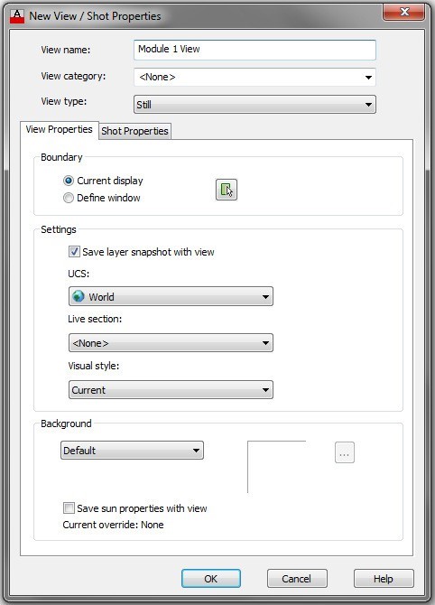
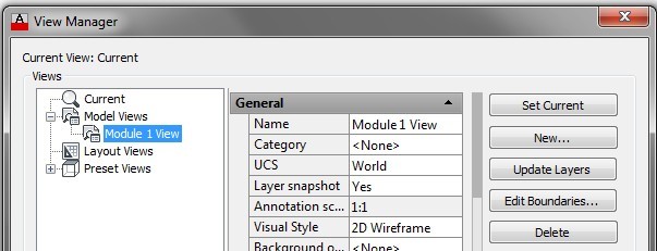
Step 16
In the Views box, click Model Views to highlight it as shown in the figure and then click the New icon. This will open the New View dialogue box. In the View name box, enter the name: Module 1 View. Click OK to see the view name as shown in the figure. Click OK to close the dialogue box. (Figure Step 16A, 16B, and 16C)
Step 17
Change the current view to SE Isometric. (Figure Step 17)
Step 18
Save and close the drawing.
Key Principles
Key Principles in Module 1
- A wireframe model is a real-world 3D object with lines, circles, arcs, and/or plines located along the edge of the A wireframe model is a hollow object.
- A model is drawn in model space. It is a 3 dimensional object drawn at full size and located accurately in relation to model space origin X0Y0Z0 in the World UCS.
- A view is simply the way you are looking at the model. It is the model displayed by the viewing angle, viewing direction, and the location of the target.
- The SE Isometric view is the home view used to keep a mental view of the model.
- Do not over-orbit the model using the orbit It best to retain a good mental view of the model at all times during model construction.
