Part 1
Module 4: User Coordinate System – Part 1
Learning Outcomes
When you have completed this module, you will be able to:
- Describe the User Coordinate System and the User Construction Plane.
- Apply the UCSMAN command.
- Draw 3D models using the User Coordinate System located at the World or at the predefined orthographic UCS locations only.
IMPORTANT – PLEASE READ BEFORE COMPLETING THIS MODULE
AutoCAD 2015 has a bug using the LINE command in 3D. The LINE command works properly when either the World or Top is the current UCS. When any other UCS is the current UCS, the cursor of the LINE command will display the new line in the wrong location. It locates the line in the correct location after you execute the LINE command. It displays correctly when snapping to existing objects and only appears wrong when using coordinates or drawing lines freehand.
A good workaround is to use the PLINE command rather than the LINE command, as it works correctly. After you complete the PLINE command, you can explode the pline to create a line object.
This bug is only in AutoCAD 2015. The LINE command in AutoCAD 2016, 2017 and 2018 works in all UCS locations.
The User Coordinate System
The User Coordinate System (UCS) is the coordinate system used to construct 3D models. It can be located at the WCS or at any location or orientation in 3D space. Being able to locate and orientate the UCS anywhere in 3D space is the secret of 3D modeling.
The User Construction Plane
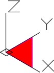
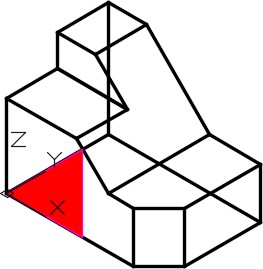
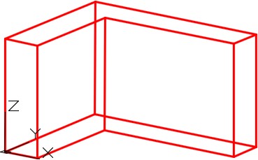
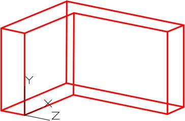
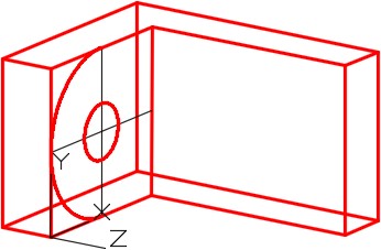
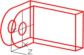
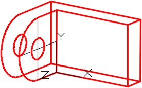
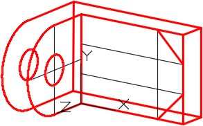
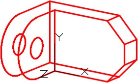
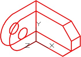
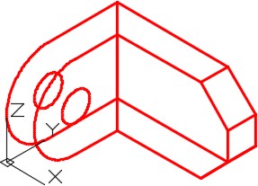
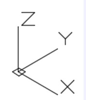
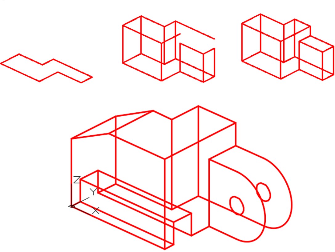
If you draw an imaginary line from the X axis to the Y axis on the user coordinate system, it forms a imaginary triangular plane as shown in Figure 4-1. When you locate the UCS onto the 3D model, as shown in Figure 4-2, you can see this imaginary triangular plane laying on the surface. Next, picture the plane expanded to fill the whole surface it is located on. See Figure 4-3. This surface is called the User Construction Plane (UCP).
User Construction Plane
The easiest method of drawing 3D models is to locate and orientate the user construction plane to lie on the surface you currently want to insert or modify object(s) on. Relocate the location of the UCS and continue your model construction until you complete the model. You can use the Z axis to copy the object(s) and draw at a depth parallel to the UCP.
User Construction Plane on the WCS
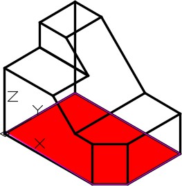
UCS Plane expanded to cover the Whole Surface
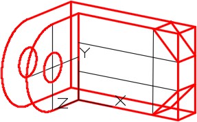
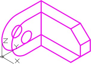
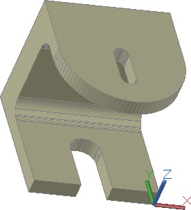
By relocating and orientating the UCS to different locations, you can draw or modify objects on any surface you want. Figure 4-4 shows the user construction plane located on the right side of the model and Figure 4-5 shows it located on the inclined surface.
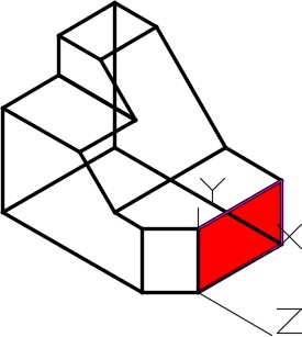
UCP located on the Right Side
In this module, all model construction will be drawn in the with the UCS located at the World or in one of the preset orthographic locations only. In Module 5, locating the UCS anywhere in model space will be taught.
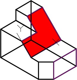
UCP located on an Inclined Surface
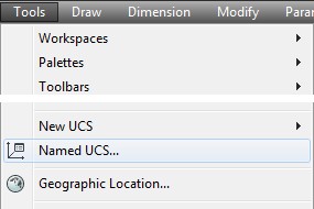
AutoCAD Command: UCSMAN
The UCSMAN command is used to locate, orientate, and manage the UCS.
Shortcut: none
WORK ALONG: Moving the UCS to the Preset Locations
Step 1
Using the NEW command, start a new drawing using the template: 3D Layout English.
Step 2
Save and name the drawing: AutoCAD 3D Workalong 04-1. Save it in the folder: CAD Courses/AutoCAD 3D/Lab Exercises
Step 3
Set the current UCS to World. Enter the UNITS command. In the Units dialogue box, set the Insertion Units to Inches. Using the INSERT command, insert the block: AutoCAD 3D Lab 01-1 at the coordinates 0,0,0. Explode the block.
Step 4
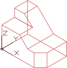
Set the current view to SE Isometric. Your wireframe model should appear as shown in the figure. (Figure Step 4)
Step 5
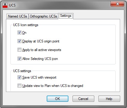
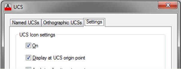
Enter the UCSMAN command. It will open the UCS dialogue box. Enable the Settings tab and ensure that the settings in the dialogue box matches the figure. (Figure Step 5)
Step 6
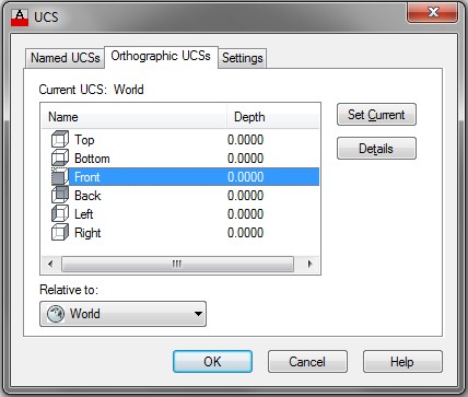
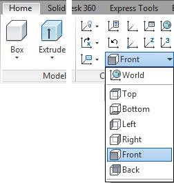
Enable the Orthographic UCS’s tab. Select Front and then click the Set Current button. (Figure Step 6)
Step 7
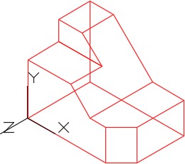
The wireframe model should now appear as shown in the figure. Notice how the XY axis lies on the front plane of the model. (Figure Step 7)
Step 8
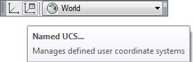
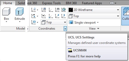
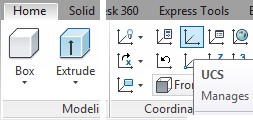
Using either the UCS II toolbar or the Home tab ribbon. (Figure Step 8A and 8B)

Step 9
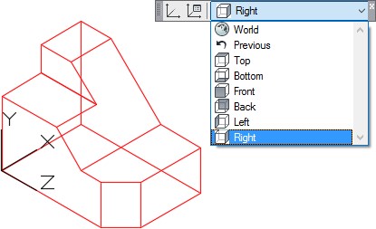
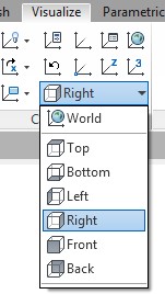
Set the current UCS location to Right and the UCS icon will move onto the right side of the model. Note that the XY plane is now located on the right side plane of the wireframe model. (Figure Step 9A and 9B)
Step 10
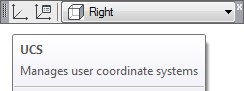
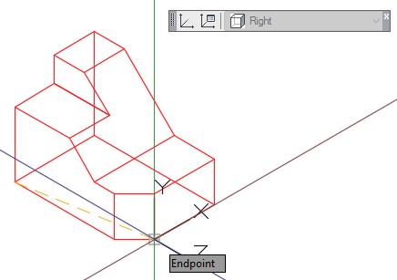
Click the UCS command icon as shown in the figures. With osnap enabled, snap to the end of the line. Note that the UCS icon has now moved to the end of the line that you just selected but it remains located on the right side plane. (Figure Step 10A, 10B, 10C, and 10D)

Step 11
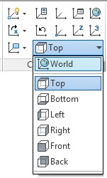
Click Top from the pull-down list. The UCS icon will move onto the top plane of the model. In this case, it locates itself on the WCS. (Figure Step 11)
Step 12
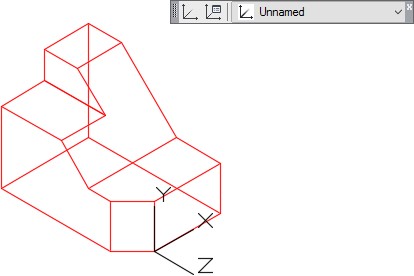
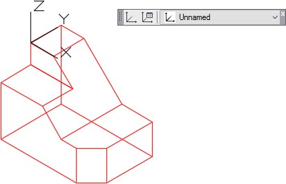
Using the UCS command, move the UCS to corner as shown in the figure. Ensure that you snap to the end of the line. Note how the name of the UCS will display ‘ Unnamed ‘. (Figure Step 12)
Step 13
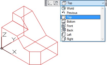
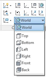
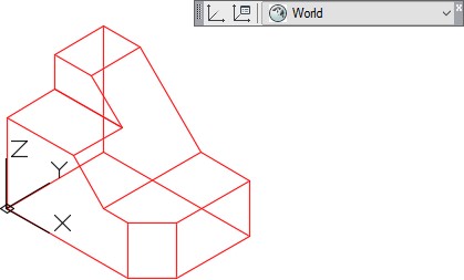
Click World from the pull-down list. The UCS icon will move onto the WCS. (Figure Step 13)
Step 14
Save and close the drawing.
WORK ALONG: Drawing 3D Wireframe Models Using the UCS
Step 1
Using the NEW command, start a new drawing using the template: 3D Layout English.
Step 2
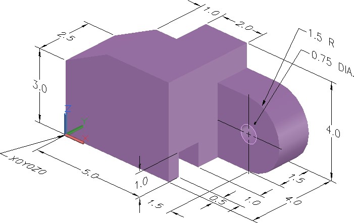
Save and name the drawing: AutoCAD 3D Workalong 04-2. (Figure Step 2A and 2B)
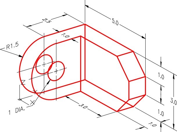
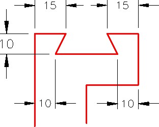
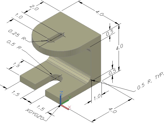
Dimension Wireframe Model
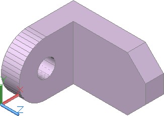
Solid Model SE Isometric View
Step 3
Ensure that the current UCS is set to World and the current view is set to SE Isometric.
Step 4
Set layer: Model as the current layer.
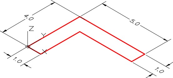
Step 5
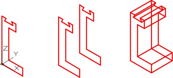
Using the LINE command, draw the lines to outline the Top view. (Figure Step 5)
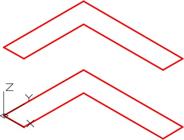
Step 6
Copy all of the lines 3 units in the positive Z direction. (Figure Step 6)
Step 7
Using the 3DFORBIT command, orbit the model slightly. (Figure Step 7)

Step 8
Using the LINE command, draw the 6 vertical lines. Ensure that you enable object snap and snap to endpoints of the existing lines. (Figure Step 8)
Step 9
Set the current UCS to Right and then locate the icon by snapping to the corner of the model as shown in the figure. (Figure Step 9)
Step 10
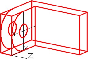
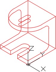
Draw the necessary construction lines using the OFFSET command. Change their layer to layer: Construction. Draw the arc and the circle. (Figure Step 10)
Step 11
Copy the arc and the circle in the negative Z direction. (Figure Step 11)
Step 12
Trim or delete necessary lines. (Figure Step 12)
Step 13
Set the current UCS to Front and then locate it to the corner as shown in the figure. (Figure Step 13)
Step 14
Draw the necessary construction lines using the OFFSET command. Change their layer to layer: Construction. Draw the object lines as shown in the figure. (Figure Step 14)
Step 15
Copy the lines in the negative Z direction and add the necessary object lines. (Figure Step 15)
Step 16
Trim or delete the necessary lines and freeze layer: Construction to complete the wireframe model. (Figure Step 16)
Step 17
Change the current view to SE Isometric. (Figure Step 17)
Step 18
Set the current UCS to World. (Figure Step 18)
Step 19
Enter the UNITS command. In the Units dialogue box, set the Insertion Units to Inches.
Insert the key: AutoCAD 3D Workalong 04-2. It will overlay the model with a magenta wireframe model. (Figure Step 19)
USER TIP: It is best to display the UCS icon at its origin point when you are constructing 3D wireframe models. See the Settings tab in the UCS dialogue box shown below.If the model is zoomed to fill the Graphic window, the UCS icon will appear to be located off the origin point. It actually is not, it simply cannot display where it should. To correct, zoom out to make the model display smaller and the icon will automatically display at the UCS origin.
MUST KNOW: The coordinate location X0Y0Z0 is always referenced to the origin of the UCS. If the UCS is located at the WCS, its origin is the absoluteX0Y0Z0. If the UCS is at any other location, the coordinates location X0Y0Z0 is the relative X0Y0Z0. To work with absolute coordinates, the UCS must be located at the WCS. Use the UCS II toolbar or the UCS dialogue box and change the UCS location to World. When the UCS is at the WCS, the icon will display a small square.
Another way to work with absolute coordinates is to place an asterisk (*) preceding the coordinate value. i.e.
@*4,0,0 specifies a point four units in the X direction of the last point entered relative to the absolute X0Y0Z0 or the WCS.
@4,0,0 specifies a point four units in the X direction of the last point entered relative to the current UCS. *0,0,0 specifies absolute X0Y0Z0 of the WCS regardless of the current location of the UCS.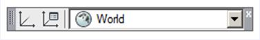
Key Principles
Key Principles in Module 4
- The User Coordinate System (UCS) is the coordinate system used to construct 3D It can be located at the WCS or at any location or orientation in 3D space. Being able to locate and orientate the UCS anywhere is the secret of 3D modeling.
- Another way to work with absolute coordinates is to place an asterisk (*) preceding the coordinate i.e.
@*4,0,0 specifies a point four units in the X direction of the last point entered relative to the absolute X0Y0Z0 or the WCS.
*0,0,0 specifies absolute X0Y0Z0 of the WCS regardless of the current location of the UCS.
Lab Exercise 4-1
Time allowed: 40 minutes.
| Drawing Name | Template | Units |
|---|---|---|
| AutoCAD 3D Lab 04-1 | 3D Layout English | Inches |
Step 1
Save and name the drawing: AutoCAD 3D Lab 04-1 as shown above.
Step 2
Draw all construction objects on layer: Construction and all model objects on layer: Model.
Step 3
Start your model with the current view in SE Isometric. If required, orbit it slightly with 3DFORBIT to help your line of sight.
Step 4
Draw a wireframe model of the object. (Figure Step 4A and 4B)
Dimensioned Solid Model
Step 5
When complete, freeze layer: Construction.
Step 6
Enter the UNITS command. In the Units dialogue box, set the Insertion Units to Inches.
Step 7
Change the current UCS to World and check the model with the key.
Hint 1
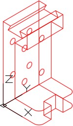
Construction Steps
Lab Exercise 4-2
Time allowed: 40 minutes.
| Drawing Name | Template | Units |
|---|---|---|
| AutoCAD 3D Lab 04-2 | 3D Layout Metric | Millimeters |
Step 1
Save and name the drawing: AutoCAD 3D Lab 04-2, as shown above.
Step 2
Draw all construction objects on layer: Construction and all model objects on layer: Model.
Step 3
Start your model with the current view in SE Isometric. If required, orbit it slightly with 3DFORBIT to help your line of sight.
Step 4
Draw a wireframe model of the object. (Figure Step 4A, 4B, and 4C)
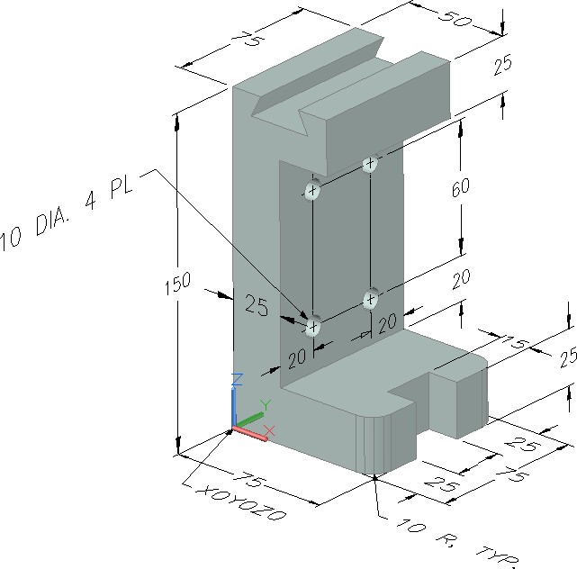
Dimensioned Solid Model
Key Detail
Step 5
When complete, freeze layer: Construction.
Step 6
Enter the UNITS command. In the Units dialogue box, set the Insertion Units to Millimeters.
Step 7
Change the current UCS to World and check the model with the key.
Hint 1
Lab Exercise 4-3
Time allowed: 40 minutes.
| Drawing Name | Template | Units |
|---|---|---|
| AutoCAD 3D Lab 04-3 | 3D Layout English | Inches |
Step 1
Save and name the drawing: AutoCAD 3D Lab 04-3, as shown above.
Step 2
Draw all construction objects on layer: Construction and all model objects on layer: Model.
Step 3
Start your model with the current view in SE Isometric. If required, orbit it slightly with 3DFORBIT to help your line of sight.
Step 4
Draw a wireframe model of the object. (Figure Step 4A, 4B, and 4C)
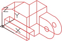
Completed Wireframe Model SE Isometric View
Step 5
When complete, freeze layer: Construction.
Step 6
Enter the UNITS command. In the Units dialogue box, set the Insertion Units to Inches.
Step 7
Change the current UCS to World and check the model with the key.
Hint 1