Part 5
Module 25 Mass Properties
Learning Outcomes
When you have completed this module, you will be able to:
- Describe and apply the MASSPROP commands to find the mass properties of solid models.
Geometry Lesson: Mass Properties
The mass properties of a solid object are its mass, centre of gravity, centroid, volume, moments of inertia, products of inertia and radii of gyration. Since the mass refers to a solid object, you can only find the mass properties of a solid model. AutoCAD expresses the mass properties in inches. The mass properties include the following:
| Mass | the quantity of the matter contained in the solid object. This is determined by the density of the material and the volume of the solid. Mass is not dependent on gravity which makes it different but proportional to weight. Mass is used when considering a measure of a solid’s resistance to inertia. |
|---|---|
| Volume | The amount of space occupied by the solid object. |
| Bounding box | The smallest possible box that the object will fit inside. The box is constructed on the XYZ axis. |
| Centroid | Geometrical centre of the object. If the density of the object is uniform, the centroid is the centre of the mass or the centre of gravity. |
| Moments of Inertia | Is the measure of how the mass is distributed around XYZ axis of the current UCS. The values in the moments of inertia are a measure of the objects resistance to angular acceleration and are used when calculating the stress on the object. |
| Products of Inertia | Similar to moments of inertia, the products of inertia measures the objects resistance to the angular acceleration, except it measures it around each 2D Axis (XY YZ XZ). |
| Radii of Gyration | If the object was a uniform solid, with no holes, the radii of gyration would be the radius the moments of inertia would use to perform its calculations around each axis. |
| Principal Moments of XYZ Direction | This is a measure of the maximum moments of inertia around an axis. When they are maximum, the principle moments are zero. |
MUST KNOW: Since AutoCAD cannot assign a material to a solid model, the volume and mass of a solid will be identical. This is because AutoCAD assigns the density of 1 to all solids. To calculate the weight of the solid model, do the following:
The formula to calculate mass or weight of the solid is:
mass= volume X density
Following is a list of the density for three common materials. You can find the density of all materials by searching for lists on the internet.
Steel – 0.2836 lb/in3
Copper – 0.3237 lb/in3
Aluminum – 0.0975 lb/in3
For example, the weight of a cubic foot of steel compared to a cubic foot of aluminum:
Steel – 1728 in3 x 0.2836 = 490.06 lbs
Aluminum – 1728 in3 x 0.0975 = 168.48 lbs
Hint: (12″X12″X12″=1728 in3)
Keep in mind that AutoCAD always works in inches.
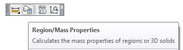
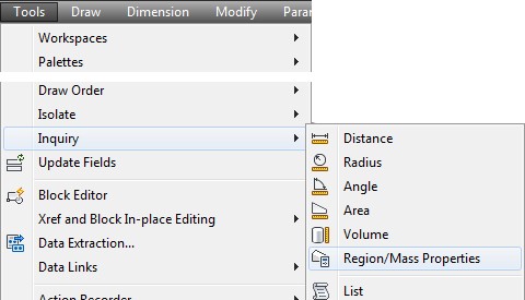
AutoCAD Command: MASSPROP
The MASSPROP command is used to compute and display the mass properties of a solid model or a region.
Shortcut: none
WORK ALONG: Finding the Mass Properties of Solids and Regions
Step 1
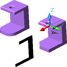
Start a new drawing using the template: 3D Layout English. Save the drawing with the name: AutoCAD 3D Workalong 25-1
Step 2
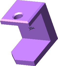
Using the INSERT command, insert the block: AutoCAD 3D Workalong 25-1 at the coordinates 0,0,0. Explode the block. Do not explode the solids. Change the solid models to layer: Solid 2.
Step 3
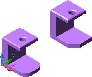
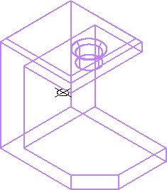
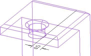
Set the current view to SE Isometric, the current UCS to World and the current visual style to Realistic. Your drawing should appear as shown in the figure. (Figure Step 3)
Step 4
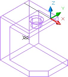
Enter the MASSPROP command, as shown below, selecting the solid model on the left side.
Command: MASSPROP
Select objects: 1 found
(Select the solid model on the left.)
Select objects:
SOLIDS
| Mass: | 19.0166 |
|---|---|
| Volume: | 19.0166Creating Solid Models Using Boxes, Wedges and Cylinder |
| Bounding box: | X: 0.0000—– 4.0000
Y: 0.0000—– 3.0000 Z: 0.0000—– 4.0000 |
| Centroid:X: | 1.1528
Y: 1.5000 Z: 1.8564 |
| Moments of inertia: | X: 159.7292
Y: 147.0995 Z: 101.3495 |
| Products of inertia: | XY: 32.8824
YZ: 52.9538 ZX: 35.1506 |
| Radii of gyration: | X: 2.8982
Y: 2.7812 Z: 2.3086 |
| Principal moments and X-Y-Z directions about centroid: | I: 52.9685 along [0.9625 0.0000 0.2712]
J: 56.2930 along [0.0000 1.0000 0.0000] K: 31.7293 along [-0.2712 0.0000 0.9625] |
Write analysis to a file? [Yes/No] <N>:
(Accept No as the default.)
Command:
Step 5
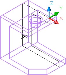
Enter the MASSPROP command again and select the solid model on the right side.
Command: MASSPROP
Select objects: 1 found
(Select the solid on the right.)
Select objects:
SOLIDS
| Mass: | 18.8792 |
| Volume: | 18.8792 |
| Bounding box: | X: 0.0000—– 4.0000
Y: 8.0000—– 11.0000 Z: 0.0000—– 4.0000 |
| Centroid:X: | X: 1.1424
Y: 9.5154 Z: 1.8485 |
| Moments of inertia: | X: 1824.7216
Y: 144.5649 Z: 1766.8808 |
| Products of inertia: | XY: 205.9529
YZ: 331.6084 ZX: 34.1723 |
| Radii of gyration: | X: 9.8312
Y: 2.7672 Z: 9.6741 |
| Principal moments and X-Y-Z directions about centroid: | I: 52.3639 along [0.9426 0.1825 0.2795]
J: 55.5396 along [-0.1827 0.9828 -0.0257] K: 31.1772 along [-0.2793 -0.0269 0.9598] |
Write analysis to a file? [Yes/No] <N>: Y
(This time enter Y to write the data to a file.)
Command:
Step 6
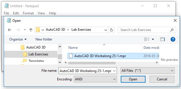
Entering Y for yes will open the Create Mass and Area Properties File dialogue box. Save the file in the Lab Exercises folder assign it the same name as the drawing. The extension .mpr is automatically added.
Step 7
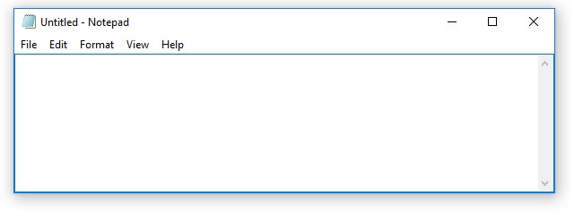
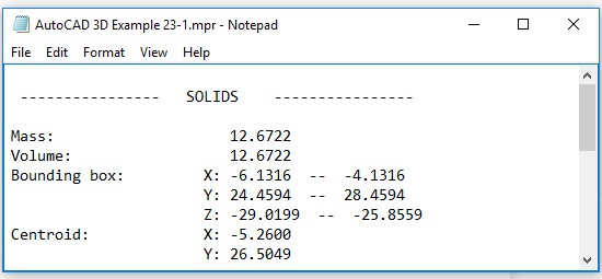
Start Notepad. (Figure Step 7)
Step 8
In Notepad, open the file: AutoCAD 3D Workalong 25-1.mpr in the folder you saved it in. (Figure Step 8A, 8B, and 8C)
Step 9
In the Notepad window, you can find the centroid as shown below. This is the centre of gravity of the model.
Centroid: X: 1.1424
Y: 9.5154
Z: 1.8485
Step 10
On layer: Construction, insert a point at the centroid of the model using the POINT command as shown below. Change the point style and your model should appear similar to the figure. The shaded model rotated also is displaying a point at the centroid. (Figure Step 10A and 10B)
Command: POINT
Current point modes: PDMODE=34
PDSIZE=0.0000
Specify a point: 1.1424,9.5154,1.8485
Command:
Step 11
Calculate and record the weight of the solid model made out of aluminum and steel. See MUST KNOW in Geometry Lesson: Mass Properties. Check your answers after Step 18.
Steel -_____________ lbs
Aluminum -________ lbs
Step 12
Using what you learned previously, offset a construction line 0.5 units from the far chamfered edge of the model on its right side. (Figure Step 12)
Step 13
Locate the Top UCS at the end of the line (Figure Step 13)
Step 14
Using what you learned in Module 20, use the SECTION command, as shown below, to create a section at the location of the construction line you just drew. (Figure Step 14)
Command: SECTION
Select objects: 1 found
Select objects: Specify first point on Section plane by
[Object/Zaxis/View/XY/YZ/ZX/3points] <3points>: ZX
Specify a point on the ZX-plane <0,0,0>:
Command:
Step 15
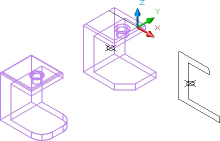
Move the region you just created outside of the model. It is not important where you locate it. Shaded and rotated, your model should appear similar to the figure. (Figure Step 15).
Step 16
Using the MASSPROP command, as shown below, find the mass properties of the region.
Command: MASSPROP
Select objects: 1 found
(Select the region.)
Select objects:
REGIONS
| Area: | 6.4844 |
| Perimeter: | 19.8536 |
| Bounding box | X: 3.8918 — 7.8918
Y: 0.0000 — 0.0000 Z: -4.0000 — 0.0000 |
| Centroid: | X: 5.0834
Y: 0.0000 Z: -2.1397 |
Write analysis to a file? [Yes/No] <N>: N
Command:
Step 17
Using what you learned earlier in this module, insert a point at the centroid of the region as shown in the figure. (Figure Step 17)
Step 18
Save and close the drawing.
Answers from Step 11
Steel – 5.3541 lbs
Aluminum – 1.8407 lbs
Key Principles
Key Principles in Module 25
- Mass properties can only be found for solid models and regions.
- The formula to calculate mass or weight of a solid is: mass= volume X density
- AutoCAD always works in inches and reports the mass properties in inches regardless of the what units the drawing was constructed in.
