Part 6
Module 28 Editing Solid Models – Part 2
Learning Outcomes
When you have completed this module, you will be able to:
- Apply the SOLIDEDIT and SOLIDCHECK commands to modify solid models.
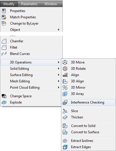
- Apply the INTERFERE command to find interferences between two or more solids.
AutoCAD Command: INTERFERE
The INTERFERE command is used to check if two or more solids occupy the same 3D space. If two or more solids occupy the same 3D space, they will interfere with one another which cannot exist in real life.
Shortcut: none
WORK ALONG: Editing Solid Models
Step 1
Using the NEW command, start a new drawing using template: 3D Layout English.
Step 2
Save the drawing and name it: AutoCAD 3D Workalong 28-1.
Step 3
Draw the plines on layer: Pline and the solid model on layer: Solid 6.
Step 4
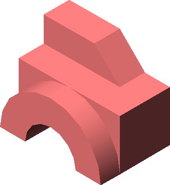
Draw a solid model of the object shown in the figures. The location of 0,0,0 is the bottom left corner of the front view. The solid model should appear as shown in the figure. (Figure Step 4A and 4B)
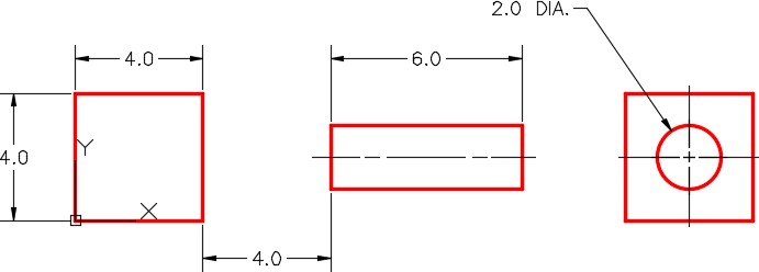
Dimensioned Multiview Drawing
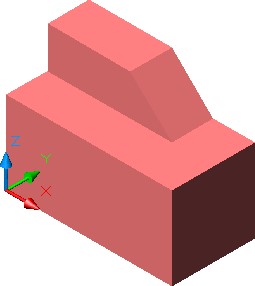
Solid Model SE Isometric View
Step 5
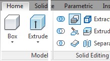
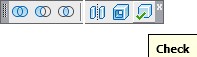
If you are using toolbars, enable the display of the Solids Editing toolbar. If you are using ribbons, use the Home tab. (Figure Step 5)


Figure Step 5
Step 6
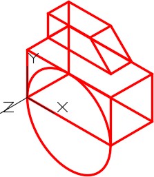
With the UCS set to Front, draw a circle by snapping to the midpoint of the bottom edge for the centre and one of the bottom corners for the radius. (Figure Step 6)
Step 7
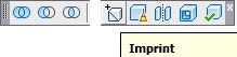
Click the Imprint icon and complete the command, as shown below, to attach the circle to the front face of the solid. (Figure Step 7A, 7B, and 7C).
Command: SOLIDEDIT
Solids editing automatic checking: SOLIDCHECK=1
Enter a solids editing option [Face/Edge/Body/Undo/eXit] <eXit>: B
Enter a body editing option
[Imprint/seParate solids/Shell/cLean/Check/Undo/eXit] <eXit>: I
Select a 3D solid: P1
(Select the solid model.)
Select an object to imprint: P2
(Select the circle.)
Delete the source object [Yes/No] <N>: Y
(Delete the original circle.)
Select an object to imprint:
Command:
Step 8
Using the Properties window, check to ensure that the arc and the solid are one solid model and not two separate objects.
Step 9
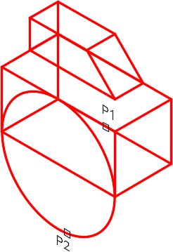
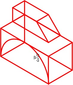
Using what you learned in Module 27, click the Extrude faces icon to extrude the arc 1 inch in the positive Z direction as shown in the command below. (Figure Step 9A and 9B)
Command: SOLIDEDIT
Solids editing automatic checking: SOLIDCHECK=1
Enter a solids editing option [Face/Edge/Body/Undo/eXit] <eXit>:F
Enter a face editing option
[Extrude/Move/Rotate/Offset/Taper/Delete/Copy/coLor/Undo/eXit] <eXit>: E
Select faces or [Undo/Remove]: P3 2 faces found.
Select faces or [Undo/Remove/ALL]: R
Remove faces or [Undo/Add/ALL]: 2 faces found, 1 removed.
Remove faces or [Undo/Add/ALL]:
Specify height of extrusion or [Path]: 1
Specify angle of taper for extrusion <0>:
Solid validation started.
Solid validation completed.
Command:

Step 10
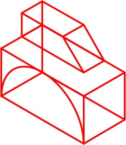
Using what you just learned, draw a 4 inch diameter circle locating its centre at the midpoint of the bottom edge. Imprint the circle to the solid to form the arc . Extrude the arc through the solid to create a slotted arc through the solid. (Figure Step 10A and 10B)
Step 11
Click the Check icon and enter the command, as shown below, to check your solid as a valid solid object. (Figure Step 11A and 11B)
Command: SOLIDEDIT
Solids editing automatic checking: SOLIDCHECK=1
Enter a solids editing option [Face/Edge/Body/Undo/eXit] <eXit>: B
Enter a body editing option
[Imprint/seParate solids/Shell/cLean/Check/Undo/eXit] <eXit>: C
Select a 3D solid:
(Select the solid model.)
This object is a valid ShapeManager solid.
(This is a valid solid.)
Enter a body editing option
Command:
Step 12
Save and close the drawing.
WORK ALONG: Finding the Interference Between Two Solids
Step 1
Using the NEW command, start a new drawing using template: 3D Layout English.
Step 2
Save the drawing and name it: AutoCAD 3D Workalong 28-2.
Step 3
Draw the plines on layer: Pline and the solid model on layer: Solid 7.
Step 4
Draw two solid models using the multiview drawing as a reference. Start the bottom left corner of the cube at 0,0,0. (Figure Step 4A and 4B)

Dimensioned Multiview Drawing
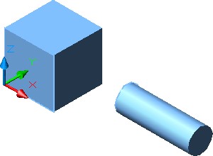
Solid Model SE Isometric View
Step 5
If you are using toolbars, enable the display of the Solids Editing toolbar. If you are using ribbons, use the Home tab. (Figure Step 5)

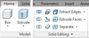
Figure Step 5
Step 6
Using the UNION command, union the two solids to make them one solid model.
Step 7
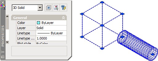
Using the Properties window, check to ensure that the two 3D Solid objects are now one 3D Solid object. (Figure Step 7)
Step 8
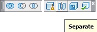
Set layer: Solid 7 as the current layer. Click the Separate icon and enter the command shown below to separate the two solids. (Figure Step 8)
Command: SOLIDEDIT
Solids editing automatic checking: SOLIDCHECK=1
Enter a solids editing option [Face/Edge/Body/Undo/eXit] <eXit>: B
Enter a body editing option
[Imprint/seParate solids/Shell/cLean/Check/Undo/eXit] <eXit>: P
Select a 3D solid:
(Select the solid.)
Enter a body editing option
Command:
Step 9
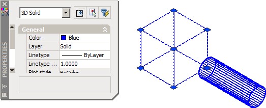
Using the Properties window, ensure that the two 3D Solid objects were separated as shown in the figure. (Figure Step 9)
Step 10
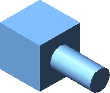
Set the current visual style to Realistic. Move the cylinder 3 inches towards the box as shown in the figure. (Figure Step 10)
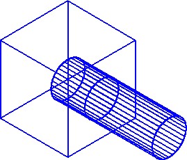
Step 11
Set the current view to SE Isometric and the current visual style to 3D Wireframe. Enter the INTERFERE command, as shown below, to find the interfering solid. (Figure Step 11)
Command: INTERFERE
Select first set of solids:
(Select one solid.)
Select objects: 1 found
Select objects:
(Press Enter)
Select second set of solids:
Select objects: 1 found
(Select the other solid.)
Select objects:
(Press Enter)
Comparing 1 solid against 1 solid.
Interfering solids (first set): 1
(second set): 1
Interfering pairs: 1
Create interference solids? [Yes/No] <N>: Y
(Enter Y.)
Command:
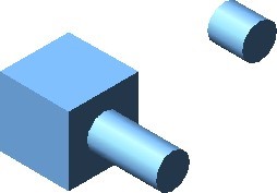
Step 12
Using the MOVE command, move the 3D Solid object created by the INTERFERE command. Where you move it is not important. (Figure Step 12)
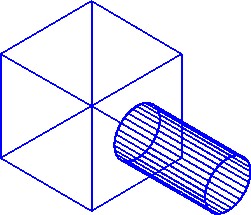
Step 13
Use the UNION command the join the two solids to one. (Figure Step 13)
Step 14
Set the current visual style to Realistic. (Figure Step 14)

Step 15
Save and close the drawing.
System Variable: SOLIDCHECK
The SOLIDCHECK system variable toggles the solid validation on and off when a solid model is selected to be edited in the SOLIDEDIT command.
When the SOLIDEDIT command is executed, the current setting of the SOLIDCHECK system variable is displayed as shown below.
Command: SOLIDEDIT
Solids editing automatic checking: SOLIDCHECK=1
(SOLIDECHECK=1 solidcheck is enabled)
(SOLIDECHECK=0 solidcheck is disabled)
Key Principles
Key Principles in Module 28
- The Separate option of the SOLIDEDIT command is used to separate two solids that have been joined together.
- The INTERFERE command is used to check if two or more solids occupy the same If two or more solids occupy the same space, they will interfere with one another and in real life could not exist.
