Part 3
Module 14: Surface Modeling – Part 3
Learning Outcomes
When you have completed this module, you will be able to:
- Describe a complex surface mesh and a region.
- Apply the 3DMESH, REGION, and SUBTRACT commands.
Drawing Complex Surface Meshes
When an irregular complex mesh cannot be drawn using a geometrically generated surface, the 3DMESH command can be used to create it. The 3DMESH command uses a grid made of XYZ coordinates to generate the surface mesh. This command is used extensively when creating 3D topographical maps. It is also used in automobile and airplane design.
AutoCAD Command: 3DMESH
The 3DMESH command is used to create an irregular complex surface mesh from a grid of XYZ coordinates.
Shortcut: none
WORK ALONG: Drawing 3D Surface Meshes
Step 1
Using the NEW command, start a new drawing using template: 3D Layout English.
Step 2
Save and name the drawing: AutoCAD 3D Workalong 14-1.
Step 3
Set layer: Model as the current layer.
Step 4
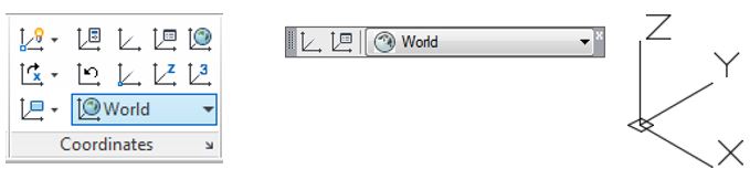
Set the current visual style to 2D Wireframe, the current UCS to World, and the current view to SE Isometric. (Figure Step 4)
Step 5
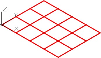
Draw a 5 X 4 grid as shown in the figure. Draw the grid lines 1 inch apart along both the X and Y axis. (Figure Step 5)
Step 6
Set layer: Surface 1 as the current layer and using Figure Step 6A as a reference, enter the 3D MESH command, as shown below, to create the 3D mesh. When complete, your drawing should appear as shown in the figure. (Figure Step 6A and 6B)
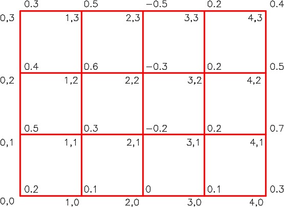
4Figure Step 6BCommand: 3DMESH
Enter size of mesh in M direction: 5
(5 columns in the X direction. Count the grid lines not the spaces.)
Enter size of mesh in N direction: 4
(4 rows in the Y direction. Count the grid lines, not the spaces.)
Specify location for vertex (0, 0): 0,0,0.2
(Enter the XYZ coordinates stating at bottom left corner which is X0Y0Z0.2. Then work up the Y axis to the top and then jump back down to X1,Y0.)
Specify location for vertex (0, 1): 0,1,0.5
(The 0.5 is entered here for clarity. If you enter .5 it will do the same thing.)
Specify location for vertex (0, 2): 0,2,0.4
Specify location for vertex (0, 3): 0,3,0.3
Specify location for vertex (1, 0): 1,0,0.1
Specify location for vertex (1, 1): 1,1,0.3
Specify location for vertex (1, 2): 1,2,0.6
Specify location for vertex (1, 3): 1,3,0.5
Specify location for vertex (2, 0): 2,0,0
Specify location for vertex (2, 1): 2,1,-0.2
Specify location for vertex (2, 2): 2,2,-0.3
Specify location for vertex (2, 3): 2,3,-0.5
Specify location for vertex (3, 0): 3,0,0.1
Specify location for vertex (3, 1): 3,1,0.2
Specify location for vertex (3, 2): 3,2,0.2
Specify location for vertex (3, 3): 3,3,0.2
Specify location for vertex (4, 0): 4,0,0.3
Specify location for vertex (4, 1): 4,1,0.7
Specify location for vertex (4, 2): 4,2,0.5
Specify location for vertex (4, 3): 4,3,0.4
Command:
Step 7
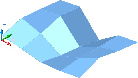
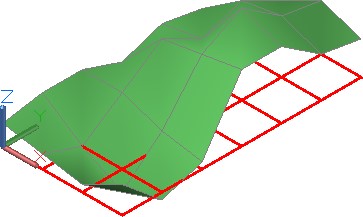
Turn layer Model off and set the current visual style to: Realistic. Your model should appear similar to the figure. (Figure Step 7)
Step 8
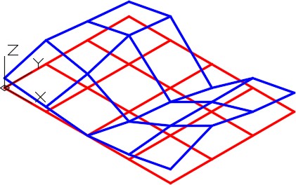
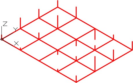
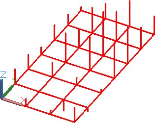
Turn layer: Surface 1 off and layer: Model on. Set the current layer to: Model. With the UCS set to World, draw lines from the each grid vertex in the Z distance. See Figure Step 6A for the Z value. Be careful as some are positive and some are negative. When the Z is 0, you do not have to draw anything. For example, the line at X0Y0 should be drawn 0.2 inches in the positive Z direction. When complete, the model should appear as shown in figure. (Figure Step 8)
Step 9
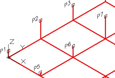
Set layer: Surface 2 as the current layer and enter the 3DMESH as shown below. (Figure Step 9)
Command: 3DMESH
Enter size of mesh in M direction: 5
Enter size of mesh in N direction: 4
Specify location for vertex (0, 0): (end) P1
(With osnap enabled, snap to the end of the Z line. You may have to zoom in to ensure you are snapping to the correct end of the line.)
Specify location for vertex (0, 1): (end) P2
Specify location for vertex (0, 2):(end) P3
Specify location for vertex (0, 3):(end) P4
Specify location for vertex (1, 0):(end) P5
Specify location for vertex (1, 1):(end) P6
(Continue until you complete the grid.)
Command:
Step 10
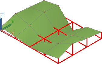
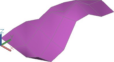
Set the current visual style to: Realistic. Your model should appear similar to the figure. (Figure Step 10)
Step 11
Save and close the drawing.
Regions
A region is a 2D solid and is created using a closed polyline, circle, ellipse or spline as the boundary. A region must lie on a 2D plane. See Figure 14-1.
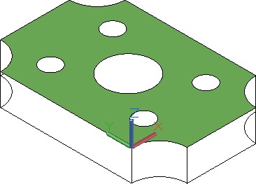
A Region
While regions are not technically surfaces, they will shade and can be rendered, therefore, can be used to surface a model.
If the system variable DELOBJ is set to 1, AutoCAD will delete the closed object that was used as the boundary to create the region. In most cases, it is important for you to set this variable to 0 to retain the original object used to create the region.
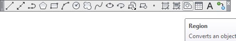
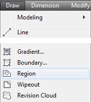
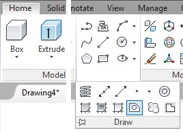
AutoCAD Command: REGION
The REGION command is used to create a 2D solid within a closed object.
Shortcut: REG
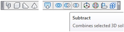
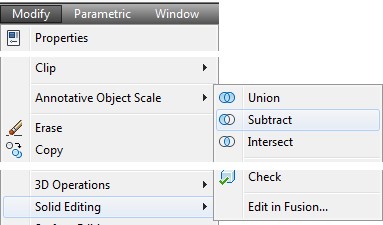
AutoCAD Command: SUBTRACT
The SUBTRACT command is used to subtract one solid from another.
Shortcut: SU
WORKALONG: Inserting and Subtracting Regions
Step 1
Using the NEW command, start a new drawing using template: 3D Layout English.
Step 2
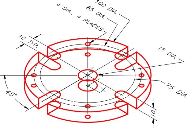
Save and name the drawing: AutoCAD 3D Workalong 14-2. (Figure Step 2)
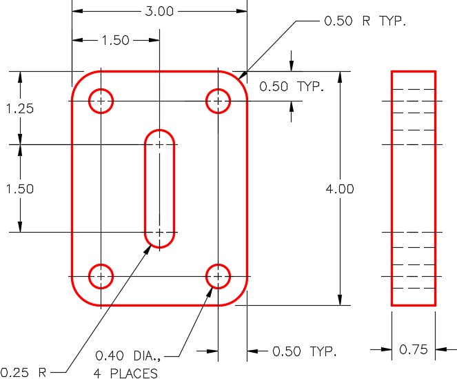
Dimensioned Multiview Drawing
Step 3
Set layer: Model as the current layer, the current view to SE Isometric, the current UCS to Top, and the current visual style to 2D Wireframe.
Step 4
Draw the wireframe model of the multiview drawing. (Figure Step 4)
Step 5
Enter the DELOBJ system variable, as shown below, and set it 0. Command: DELOBJ
Enter new value for DELOBJ <1>: 0
Command: DELOBJ
Enter new value for DELOBJ <0>:
Command:
Step 6
Move the UCS to lie on top of the model as shown in the figure. Ensure that the positive Z axis is up and it is located at the centre of the circle. (Figure Step 6)
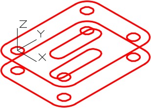
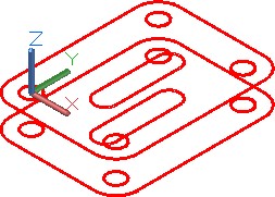
Step 7
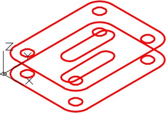
Using what you learned earlier, use the PEDIT command to convert the lines and arcs to closed polylines. Check the objects with the Properties window to ensure that they are closed. (Figure Step 7)
Step 8
Delete all of the objects except the circles on the bottom of the model and then copy the plines you just created to the bottom. (Figure Step 8)
Step 9
Set layer: Surface 1 as the current layer and enter the REGION command, as shown below, to create regions for the five closed objects on top of the model.
Command: REGION
Select objects: 1 found
(Select each object, by picking them one at a time.)
Select objects: 1 found, 2 total
Select objects: 1 found, 3 total
Select objects: 1 found, 4 total
Select objects: 1 found, 5 total
Select objects:
5 loops extracted.
5 Regions created.
Command:
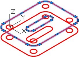
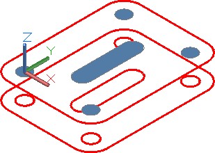
Step 10
Set the current visual style to: Realistic. Your model should appear as shown in the figure. (Figure Step 10)
Step 11
Using the REGION command, insert a region using the outside closed polyline. (Figure Step 11)
Step 12
Using the SUBTRACT command, subtract the five inner regions that you created in Step 9 from the region you created in Step 11. (Figure Step 12)
Command: SUBTRACT
Select solids and regions to subtract from ..
Select objects: 1 found
(Select the large region.)
Select objects:
(Press Enter to indicate you have finished selecting.)
Select solids and regions to subtract ..
Select objects: 1 found
(Select each of the five smaller regions one at a time.)
Select objects: 1 found, 2 total
Select objects: 1 found, 3 total
Select objects: 1 found, 4 total
Select objects: 1 found, 5 total
Select objects:
Command:
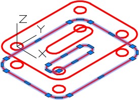
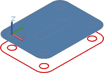
Step 13
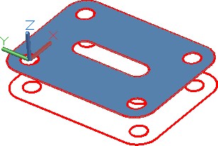
Ensure that layer: Surface Off is off and then change the layer of the region you just created to layer: Surface Off. Your model will now appear as shown in the figure. (Figure Step 13)
Step 14
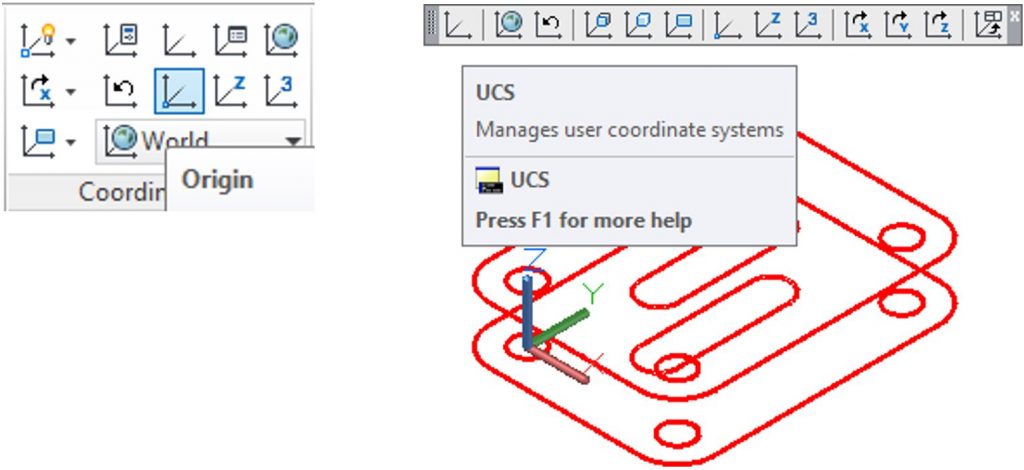
Click the UCS Origin icon and then snap to the centre of the circle on the bottom of the object. (Figure Step 14)
Step 15
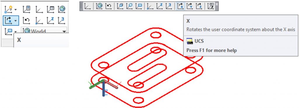
Click the Rotate X Axis UCS icon on the UCS toolbar and rotate it 180 degree rotation. This will rotate the UCS so that the positive Z direction is pointing down. (Figure Step 15)
Step 16
Using the 3DORBIT command, rotate the model around about 180 degrees and then using what you learned in Steps 10 to 12, insert the regions on the bottom. Subtract the inner regions as you did before. (Figure Step 16)
Step 17
Change the layer of the regions to layer: Surface Off and then using the RULESURF command, create surfaces on the edges and holes in the model. Create the surfaces on layer: Surface 1. (Figure Step 17)
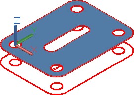
Step 18
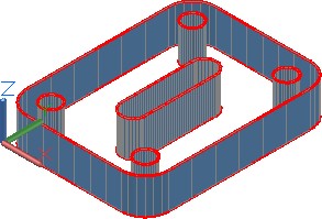
Turn layers: Model and Construction off and change the layer of the regions to layer: Surface 1. Your completed model should appear as shown in the figure. Use the 3DORBIT command to check that the complete model is surfaced. (Figure Step 18)
Key Principles
Key Principles in Module 14
- A region is a two-dimensional solid created using a closed polyline, circle, ellipse, or spline as the Each region must lie on one plane.
- While regions are not technically surfaces, they will shade and can be rendered, therefore, can be used to surface a A shaded region will only be visible when viewed from the positive Z direction of the UCS that was current when the region was created.
Lab Exercise 14-1
Time allowed: 60 minutes.
| Drawing Name | Template | Units |
|---|---|---|
| AutoCAD 3D Lab 14-1 | 3D Layout Metric | Millimeters |
Step 1
On layer: Model, draw the grid shown below. The grid lines are an equal distance apart. (Figure Step 1A and 1B)
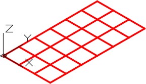
Grid in SE Isometric View
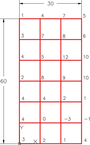
Grid in Top View
Step 2
On layer: Surface 2, draw a 3D mesh on the grid using the 3D MESH command. The Z values are displayed at each vertex in Figure Step 1B. Set the current visual style to Realistic. It should appear as shown in the figure. (Figure Step 2)
Step 3
Set the current visual style to 3D Wireframe. Turn layer Surface 2 off and on layer: Model, draw lines representing the Z coordinates. (Figure Step 3)
Step 4
On layer: Surface 3, draw a 3D mesh on the grid using the 3D MESH command and snapping to ends of the Z coordinates. Set the current visual style to Realistic. (Figure Step 4)

Step 5
Turn layer: Model off and the completed mesh should appear as shown in the figure. (Figure Step 5)
Step 6
Set the Insertion Units, change the current UCS to World and check the model with the key.
Step 7
Save and close the drawing.
Lab Exercise 14-2
Time allowed: 40 minutes.
| Drawing Name | Template | Units |
|---|---|---|
| AutoCAD 3D Lab 14-2 | 3D Layout Metric | Millimeters |
Step 1
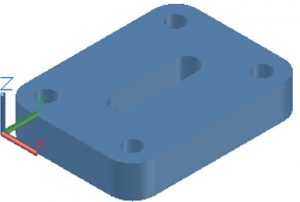
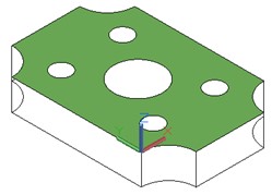
Draw a wireframe model of the object. (Figure Step 1A and 1B)

Completed Surfaced Model
Dimensioned Wireframe Model
Step 2
Use the 2D ARRAY command to speed the model construction.
Step 3
On layer: Surface 1, create regions for the top and bottom of the model.
Step 4
On layer: Surface 1, create ruled surfaces for the remainder of the surfaces. Ensure that the complete model is surfaced.
Step 5
Set the visual style to: Realistic.
Step 6
Freeze layers: Construction and Model.
Step 7
Using the 3DORBIT command, check the model for completeness
Step 8
Set the Insertion Units, change the current UCS to World and check the model with the key.
Lab Exercise 14-3
Time allowed: 30 minutes.
| Drawing Name | Template | Units |
|---|---|---|
| AutoCAD 3D Lab 14-3 | N/A | Millimeters |
Step 1
Open the drawing: AutoCAD 3D Lab 03-2.
Step 2
Save the drawing with the name: AutoCAD 3D Lab 14-3.
Step 3
On layer: Surface 1, create regions and surfaces on all sides and holes. (Figure Step 3)
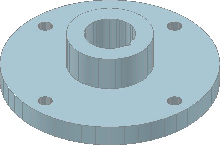
Completed Surfaced Model
Step 4
Set the visual style to Realistic.
Step 5
Freeze layers: Construction and Model.
Step 6
Using the 3DORBIT command, check the model for completeness
Step 7
Save and close the drawing.
Lab Exercise 14-4
Time allowed: 50 minutes.
| Drawing Name | Template | Units |
|---|---|---|
| AutoCAD 3D Lab 14-4 | N/A | Inches |
Step 1
Open the drawing: AutoCAD 3D Lab 09-3.
Step 2
Save the drawing with the name: AutoCAD 3D Lab 14-4.
Step 3
On layer: Surface 2, create regions and surfaces on all sides and holes. (Figure Step 3)
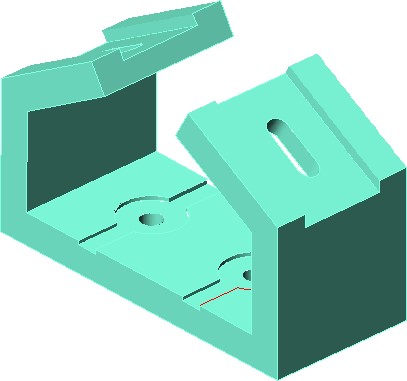
Completed Surfaced Model
Step 4
Set the visual style to: Realistic.
Step 5
Freeze layers: Construction and Model.
Step 6
Using the 3DORBIT command, check the model for completeness
Step 7
Save and close the drawing.
