Part 4
Module 20 Sectioning Solid Models
Learning Outcomes
When you have completed this module, you will be able to:
- Apply the SLICE command to cut solid models into two individual solids.
- Apply the SECTION command to create 2D cross sectional regions through solid models.
Sectioning
The SLICE and SECTION commands are used to create cross sections from solid models. They can be very useful commands and save you drawing time.
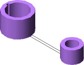
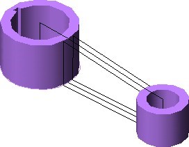
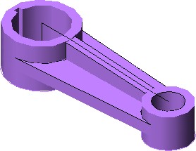
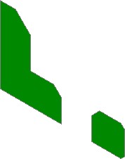
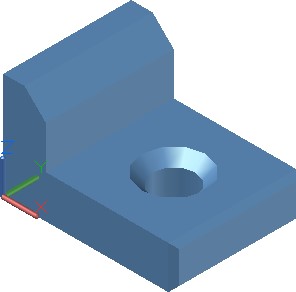
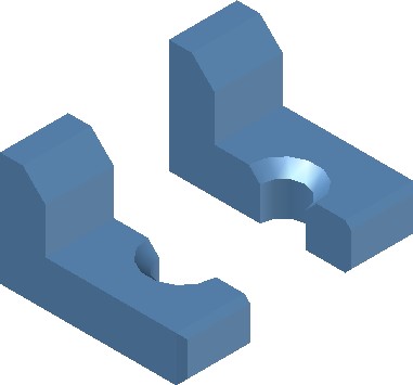
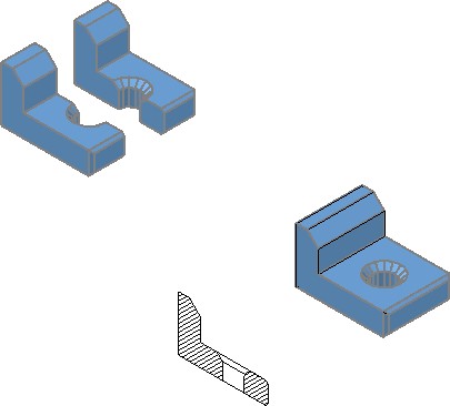
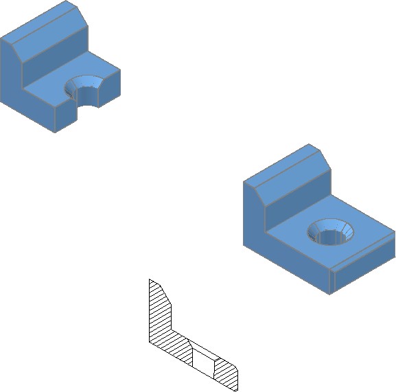
The SLICE command, see Figure 20-1A and 20-1B, cuts a solid model into two individual solids.
Before Slice
After Slice
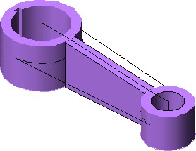
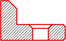
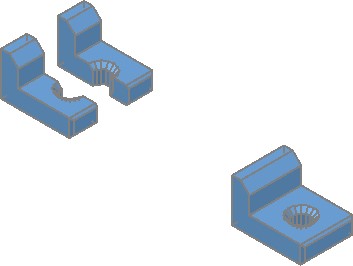
The SECTION command, see Figure 20-2, creates a two dimensional region along a selected cutting plane. The region can then be relocated to produce a cross section view in 2D and used as a detail drawing. See Figure 20-3 and 20-4.
Section
AutoCAD Command: SLICE
The SLICE command is used to cut a solid into two individual solids.
Shortcut: none
AutoCAD Command: SECTION
The SECTION command is used to create a two- dimensional region along a specified plane in a solid object.
Shortcut: SEC
WORK ALONG: Sectioning Solid Models
Step 1
Using the NEW command, start a new drawing using template: 3D Layout English.
Step 2
Save and name the drawing: AutoCAD 3D Workalong 20-1.
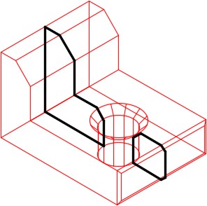
Step 3
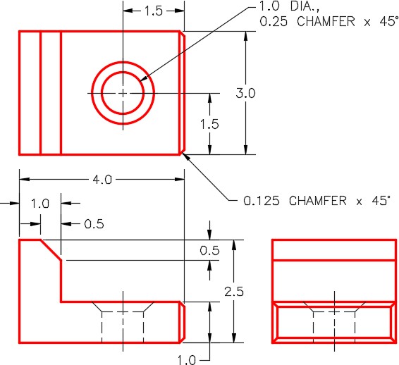
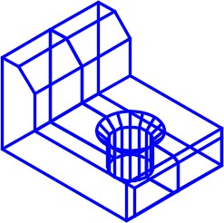
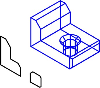
Using the figures as a reference, draw the closed plines on layer: Pline. (Figure Step 3)
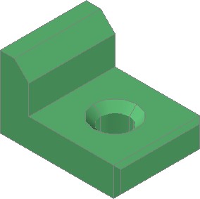
Step 4
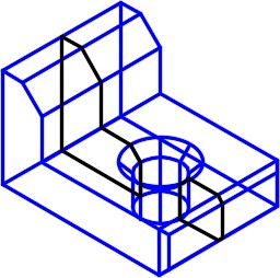
Draw the solid model on layer: Solid 7. (Figure Step 4)

Step 5
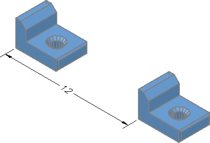
Turn layer: Pline off. Set the current UCS set to World and make a copy of the solid model 12 inches along the X axis. (Figure Step 5)
Step 6
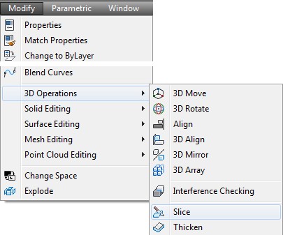
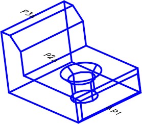
Set the current visual style to 2D Wireframe. On the original solid model, enter the SLICE command, as shown below, to slice it into two parts. (Figure Step 6A and 6B)
Command: SLICE
Select objects: 1 found
(Select the solid model.)
Select objects:
(Press Enter.)
Specify first point on slicing plane by [Object/Zaxis/View/XY/YZ/ZX/3points] <3points>: (mid) P1
Specify second point on plane: (mid) P2
Specify third point on plane: (mid) P3
(Ensure you snap to the midpoint of each edge. If you drew an imaginary line from P1 to P2 to P3 and back to P1, it would form a cutting plane. You will have to orbit the model to do this.)
Specify a point on desired side of the plane or [keep Both sides]: B
(Enter B to retain both sides of the slice.)
Command:
Step 7
Change the current visual style to Realistic. (Figure Step 7)
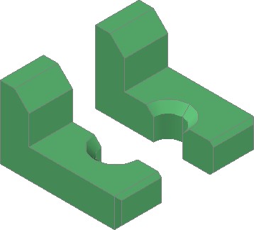
Step 8
Using the MOVE command, move the right half away from the left half. The distance you move it is not important. (Figure Step 8)
Step 9
Your model should now appear similar to the figure. (Figure Step 9)
Step 10
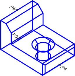
Set the current visual style to 2D Wireframe and set layer: Hatch as the current layer. Using the copied solid, enter the SECTION command, as shown below, to create a cross section. (Figure Step 10A and 10B)
Command: SECTION
Select objects: 1 found
(Select the solid.)
Select objects:
Specify first point on Section plane by
[Obj/Zaxis/View/XY/YZ/ZX/3points] <3points>: (mid) P4
Specify second point on plane: (mid) P5
Specify third point on plane: (mid) P6
Command:
Step 11
Using the MOVE command move the region, that you just created, outside of the solid. The distance you move it is not important. (Figure Step 11)
Step 12
Explode the region to convert it to lines. On layer: Hatch, add the lines to complete the cross section view as shown the figure. (Figure Step 12)
Step 13
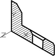
Set the current UCS to Front, the visual style to 2D Wireframe and set layer: Hatch as the current layer. Using the HATCH command, insert the hatch pattern ANS131. (Figure Step 13)
Step 14
Your drawing should now appear similar to the figure. (Figure Step 14)
Step 15
Move the original solid back together using osnap to locate it exactly. Use the UNION command to join the two halves into one solid model. Using the Properties window, check to ensure that you only have one solid object. (Figure Step 15)
Step 16
Set the current UCS to Right and the visual style to 2D Wireframe. (Figure Step 16)
Step 17
Enter the SLICE command, as shown below, to cut the solid through the centre of the hole on the XY plane. (Figure Step 17)
Command: SLICE
Select objects: 1 found
(Select the solid.)
Select objects: Specify first point on slicing plane by
[Object/Zaxis/View/XY/YZ/ZX/3points] <3points>: XY
(The XY plane is selected to be the cutting plane. All that is required now is a point and the slice will occur. It will then slice at this point parallel to the XY plane.)
Specify a point on the XY-plane <0,0,0>: (cen) of P7
(The centre of the circle is the point selected. The solid will be sliced through centre of the circle, parallel to XY plane.)
Specify a point on desired side of the plane or [keep Both sides]: P8
(Only the left side is kept.)
Command:
Step 18
Set the current UCS to World and the current visual style to Realistic. (Figure Step 18)
Step 19
Save and close the drawing.
Key Principles
Key Principles in Module 20
- The SLICE command cuts a solid model into two individual solids.
- The SECTION command creates a two dimensional region along a selected cutting plane. The region can then be relocated to produce a cross section view in 2D and used as a detail drawing.
Lab Exercise 20-1
Time allowed: 60 minutes.
| Drawing Name | Template | Units |
|---|---|---|
| AutoCAD 3D Lab 20-1 | 3D Layout Metric | Millimeters |
Step 1
Draw the closed plines on layer: Pline.
Step 2
On layer: Solid 3, draw a solid model of the object shown in the figures. (Figure Step 2A and 2B)
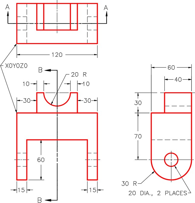
Dimensioned Multiview Drawing
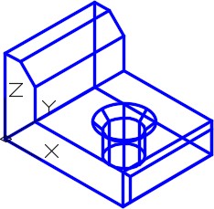
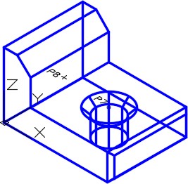
Step 3
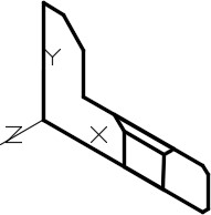
Set the Insertion Units, change the current UCS to World and check the model with the key.
Step 4
On layer: Hatch, using the SECTION command, create a region at the cutting plane A-A. Crosshatch it with ANSI31. (Figure Step 4)
Step 5
Set the current UCS to World, make a copy of the solid model 180 millimeters apart in the X direction. Do not copy the region with the solid.
Step 6
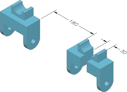
Slice the model into two solids at cutting plane B-B. Move the two solids 30 millimeters apart. (Figure Step 6)
Step 7
Save and close the drawing.
Lab Exercise 20-2
Time allowed: 60 minutes.
| Drawing Name | Template | Units |
|---|---|---|
| AutoCAD 3D Lab 20-2 | 3D Layout Metric | Millimeters |
Step 1
Draw the closed plines on layer: Pline.
Step 2
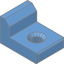
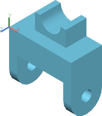
On layer: Solid 2, draw a solid model of the object shown in the figures. (Figure Step 2A and 2B)
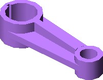
Completed Solid Model
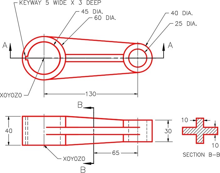
Dimensioned Multiview Drawing
Step 3
Set the Insertion Units, change the current UCS to World and check the model with the key.
Step 4
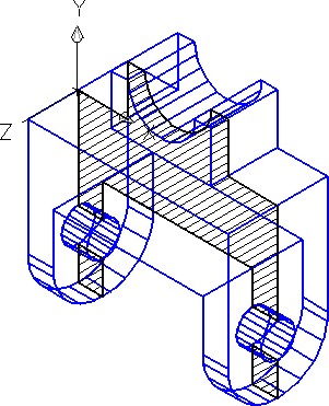
On layer: Hatch, create a 2D region section at the cutting plane B-B. Move the region away from the model and hatch it with ANS131. (Figure Step 4)
Step 5
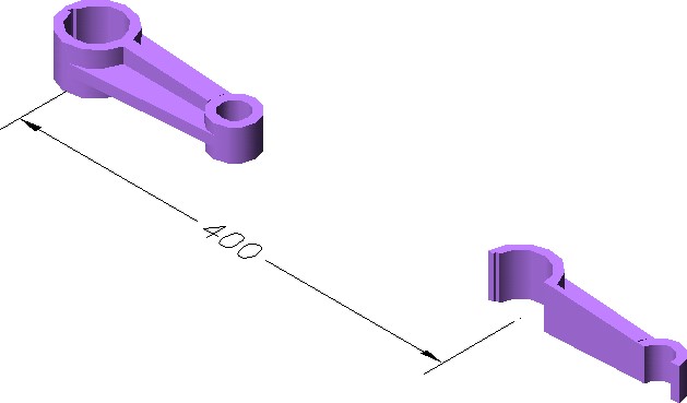
Set the current UCS to World and make a copy of the solid model 400 millimeters from centre to centre in the X direction.
Step 6
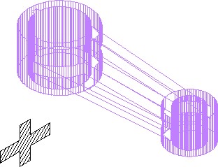
Slice the model into two solids at cutting plane A-A. Keep only the back half of the slice. (Figure Step 6)
Step 7
Save and close the drawing.
Hint 1