Part 5
Module 26 Competency Test No.5 Open Book
Learning Outcomes
When you have completed this module, you will be able to:
- Within a three hour time limit, complete a written exam and the lab exercise without the aid of a key.
The AutoCAD 3D book was written with competency based modules. What that means is that you have not completed each module until you have mastered it. The Competency Test module contains multiple choice questions and a comprehensive lab exercise to test your mastery of the set of modules that you completed. There are no answers or keys supplied in a Competency Test module since it is meant to be checked by your instructor. If there are any parts of this module that you have trouble completing, you should go back and reread the module or modules containing the information that you are having trouble with. If necessary, redo as many lab exercises required until you fully understand the material.
If you are completing this book:
- Without the aid of an instructor, complete the written test and the lab exercise.
- In a classroom with an instructor, the instructor will give instructions on what to do after this module has been completed.
Multiple Choice Questions
Select the BEST answer.
- For which AutoCAD objects can Mass Properties be found?
- Wireframes and Solids
- Regions and Faces
- Solids and Regions
- Regions and Wireframes
- Edges and Faces
- What command is used to create a solid model by moving a profile along a selected path?
- LOFT
- SHELL
- HELIX
- SWEEP
- MOVEP
- What formula is used to find the weight of a solid object?
- inertia x mass + density
- density x mass
- volume + density
- mass x volume
- volume x density
- By default, what extension file name will be assigned to the mass properties report generated from the MASSPROP command?
- .MRP
- .MAP
- .TGA
- .MPR
- .MPP
- What system variable setting controls if the original profile and path geometry are kept or deleted after being selecting in the SWEEP command?
- DBMODE
- ISOLINES
- DELOBJ
- SURFTAB
- OBJDEL
- What command is used to create a coil?
- HELIX
- SHELL
- LOFT
- SWEEP
- MOVEP
- What command is used to create a solid by blending two or more cross sections, that are closed objects, of different shapes?
- SHELL
- LOFT
- HELIX
- SWEEP
- MOVEP
- Which one of the following objects cannot be used as a path for the SWEEP command?
- 2D Polyline
- Ellipse
- Circle
- Trace
- 3D Polyline
- Which two of the following commands are most important commands used to create a thread?
- LOFT and SHELL
- SHELL and HELIX
- HELIX and SWEEP
- SWEEP and LOFT
- MOVEP and HELIX
- When creating a thread, which one of the following objects is used as the path in the SWEEP command?
- Arc
- Circle
- Helix
- 3D Spline
- 3D Polyline
Lab Exercise 26-1 OPEN BOOK
| Drawing Name | Template | Units |
|---|---|---|
| AutoCAD 3D Lab 26-1 | 3D Layout English | Inches |
Step 1
Complete the following steps to draw the individual solid models and assemble them. They can be drawn anywhere in model space. (Figure Step 1A and 1B)
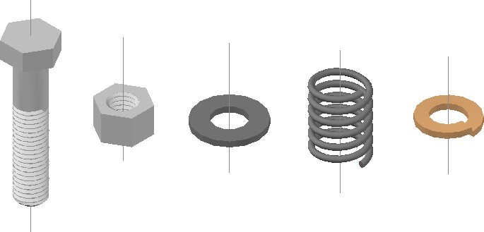
Completed Solid Models – SE Isometric View
Step 2
Set the system variable DELOBJ to 0.
Step 3
For all solid models, draw the profiles on layer: Profile, the paths on layer: Path, the helixes on layer: Helix, the plines on layer: Pline, and the centre lines on layer: Center Line.
Step 4
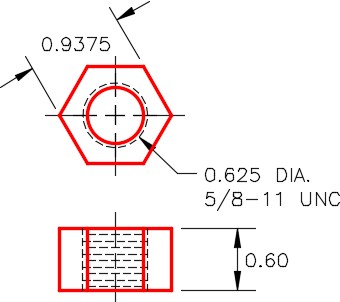
Draw a solid model of the bolt on layer: Solid 9 using the dimensioned drawings as a reference. Draw a centre line in the model. (Figure Step 4A, 4B, and 4C)
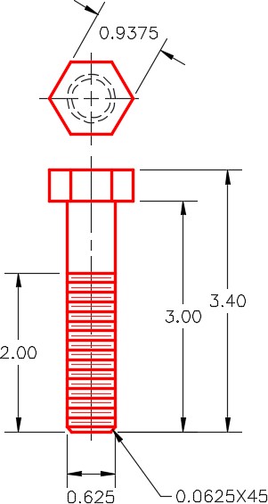
Dimensioned Multiview Drawing of Bolt
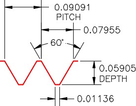
Dimensioned Thread Details
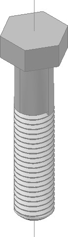
Bolt –
SE Isometric View
Step 5
Draw a solid model of the nut on layer: Solid 9 using the dimensioned drawing as a reference. Draw a centre line in the model. (Figure Step 5A and 5B)
Dimensioned Multiview Drawing of Nut
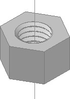
Nut –
SE Isometric View
Step 6
Draw a solid model of the washer on layer: Solid 8 using the dimensioned drawing as a reference. Draw a centre line in the model. (Figure Step 6A and 6B)
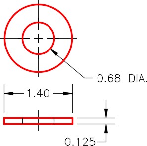
Dimensioned Drawing of Washer
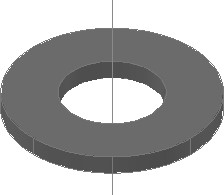
Washer –
SE Isometric View
Step 7
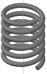
Draw a solid model of the spring on layer: Solid 8 using the dimensioned drawing as a reference. Draw a centre line in the model. (Figure Step 7A and 7B)
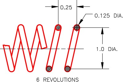
Dimensioned Drawing of Spring
Step 8
Draw a solid model of the lock washer on layer: Solid 4 using the dimensioned drawing as a reference. Draw a centre line in the model. (Figure Step 8A, 8B, and 8C)
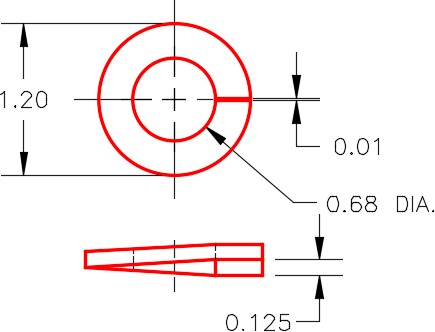
Dimensioned Multiview Drawing of Lock Washer
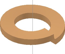
Lock Washer – SE Isometric View
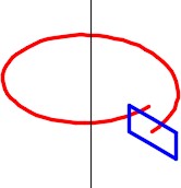
Helix Hints Turn Height – 0.130
Turns – 0.99
Step 9
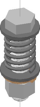
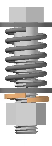
Using the centerlines as guide, copy the solid models to create an assembly solid model. After you assemble all the parts, by snapping to the centerlines. Change the current view to Right, the current UCS to Right and with Ortho enabled, move the parts ,by eye, to locate them vertically. (Figure Step 9A and 9B)
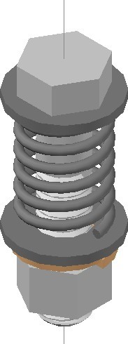
Assembly –
SE Isometric View
Step 10
Save and close the drawing.
