Part 1
Module 5: User Coordinate System – Part 2
Learning Outcomes
When you have completed this module, you will be able to:
- Describe and apply the UCS command to locate and orientate the UCS to any location necessary for model construction.
- Draw 3D models using the UCS command to locate and orientate the UCS.
Locating the UCS in 3D Space
In Module 4, the UCSMAN command and the UCS II toolbar or ribbon were used to locate the UCS at preset orthographic locations on the model. In this module, the UCS command and the UCS toolbar or ribbon will be used to move and orientate the UCS to locations that are required to construct more complicated models. The most useful option is locating the UCS by selecting 3 points on the model. While it is still necessary to use the predefined orthographic UCS locations for model construction, not all models can be built using only them.
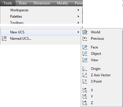
AutoCAD Command: UCS
The UCS command is used to locate and orientate the UCS on the model or in model space.
Shortcut: none
WORK ALONG: Locating and Orientating the UCS Using the UCS Toolbar
Step 1
Using the NEW command, start a new drawing using the template: 3D Layout English.
Step 2
Save and name the drawing: AutoCAD 3D Workalong 05-1.
Step 3
Set the UCS to World. Enter the UNITS command and in the Units dialogue box, set the Insertion Units to Inches. Using the INSERT command, insert the block: AutoCAD 3D Lab 01-1 at the coordinates 0,0,0.
Step 4
Explode the block you inserted in step 3.
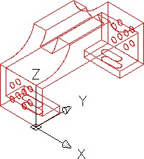
Step 5
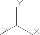
Set the current view to SE Isometric. Your model should appear as shown in the figure. (Figure Step 5).
Step 6
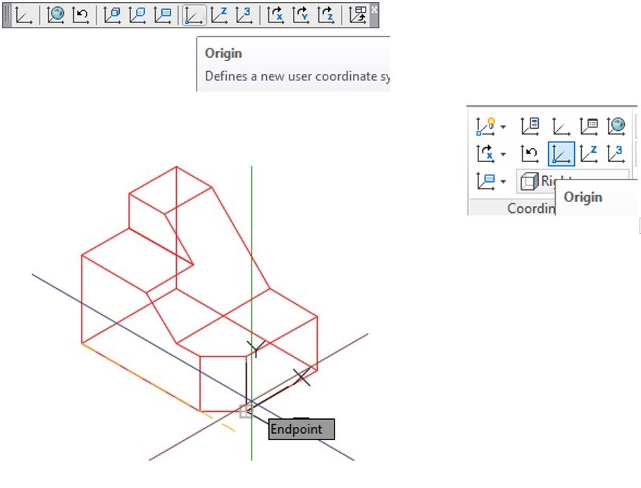
Set the UCS location to Right. (Figure Step 6)
Step 7
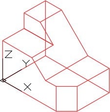
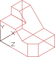
Click the Origin icon and then snap to the end of the line shown in Figure Step 7A. Your model should now appear as shown in the figure. (Figure Step 7A and 7B)
Step 8
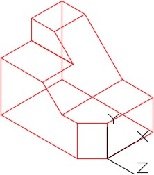
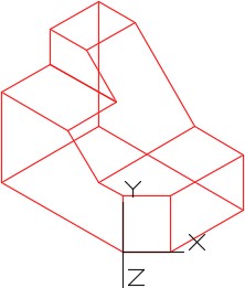
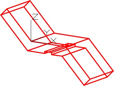
Enable object snap. Click the 3 Point icon. When prompted, select the end of the inclined line. This is the X0Y0Z0 of the UCS. (Figure Step 8)
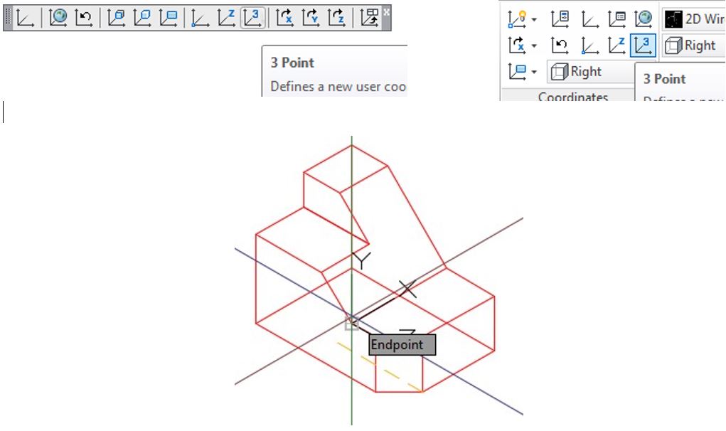
Step 9
For the second point, select end of the inclined line on the right side of the model. This is the positive X axis. (Figure Step 9)
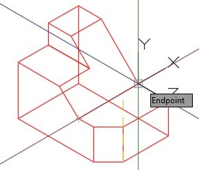
Step 10
For the third point, select the end of the inclined line on the top. This is the positive Y axis. Your model should now appear as shown in the figure. (Figure Step 10A and 10B)
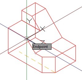
Step 11
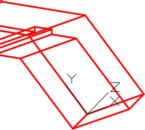
Using what you learned in Steps 8 to 10, locate the UCS as shown in the figure. Ensure that the UCS plane lies on the inclined plane. (Figure Step 11)
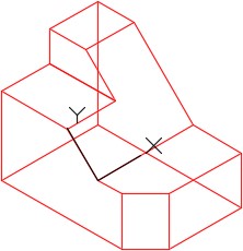
Step 12
Using what you learned in Step 8 to 10, locate the UCS as shown in the figure. Ensure that the UCS plane lies on the plane. (Figure Step 12.)
Step 13
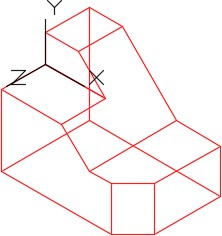
Click the World UCS icon. The UCS icon will now be located as shown in the figure. (Figure Step 13)
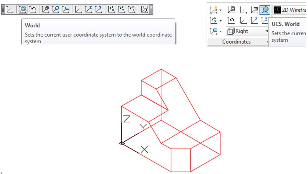
Step 14
Click the UCS Previous icon and the UCS should now return back to last location. (Figure Step 14)
Step 15
Save and close the drawing.
WORK ALONG: Drawing a 3D Wireframe Model by Locating the UCS
Step 1
Using the NEW command, start a new drawing using the template: 3D Layout Metric.
Step 2
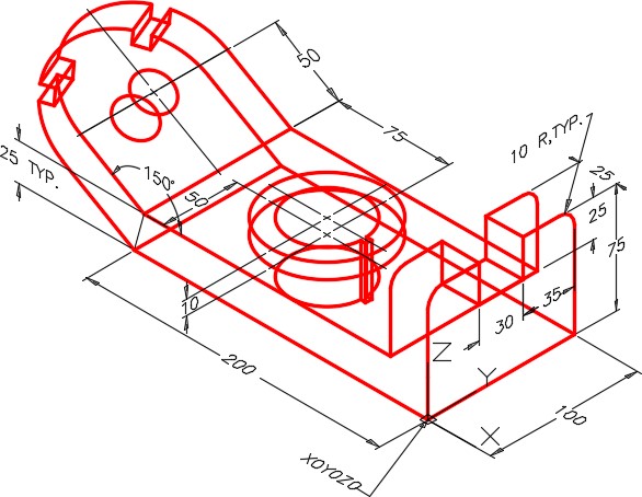
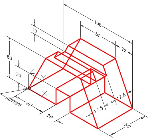
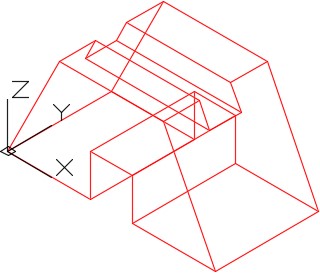
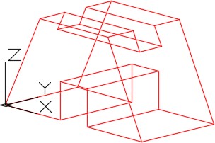
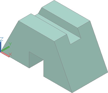
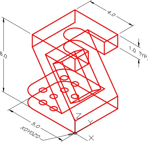
Save and name the drawing: AutoCAD 3D Workalong 05-2. (Figure Step 2A, 2B, and 2C)
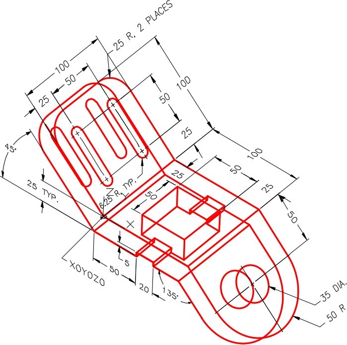
Dimensioned Wireframe Model SE Isometric View
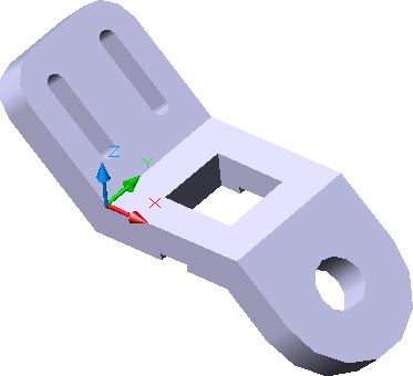
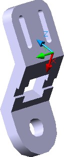
Solid Model – View from Bottom.
Step 3
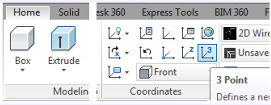
If you are using toolbar menus, you will be using the UCS, UCS II, and View toolbars. If you are using ribbon menus, enable the Home tab.
Step 4
Ensure that the UCS is located at World. (Figure Step 4)
Step 5
Change the UCS location to Front. (Figure Step 5)
Step 6
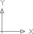
Change the current view to Front. The UCS icon should now appear as shown in the figure. (Figure Step 6)
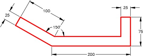
Step 7
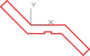
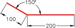
Set layer: Model as the current layer. Draw the front contour of the model as shown in the figure. Drawing it in 2D is sometimes easier. It could have been drawn in the 3D view also. (Figure Step 7)
Step 8
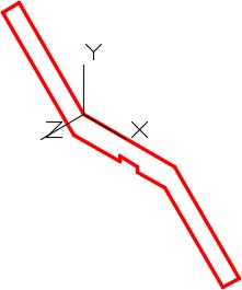
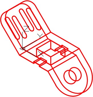
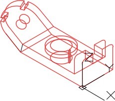
Change the current view to SE Isometric. Your model should now appear as shown in the figure. (Figure Step 8)
Step 9
Copy the lines 100 millimeters in the negative Z direction.
Step 10
Orbit the model slight as shown in the figure. Add the lines as shown in the figure. (Figure Step 10)
Step 11
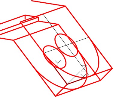
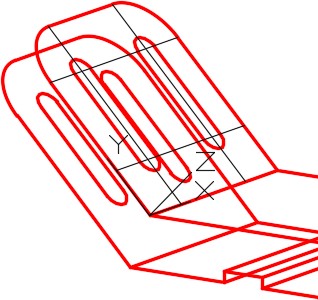
Using the 3 Point method, locate the UCS to the top of the inclined plane. (Figure Step 11)
Step 12
Using OFFSET command, offset the existing lines to locate the centre of the circle and arc on the inclined plane. Change the lines to layer: Construction. Insert the circle and the arc and copy them 25 millimeters to the bottom plane. Before you do complete this step, read the User Tip at the end of this workalong. (Figure Step 12)
Step 13
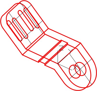
Trim or delete the lines as required. Using the 3 Point method, locate the UCS to the upper incline plane. (Figure Step 13)
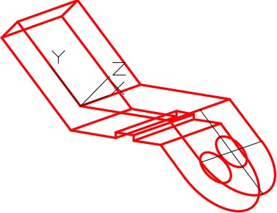
Step 14
Using the OFFSET command, offset the existing lines to locate the centre of the slots on the upper inclined plane. Change the offset lines to layer: Construction. Draw the slots and copy them 25 units to the bottom of the inclined plane. (Figure Step 14)
Step 15
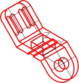
Using the 3 Point method, locate the UCS to the top plane. (Figure Step 15)
Step 16
Construct the square hole, copy it and trim the lines. (Step 16A and 16B)
Step 17
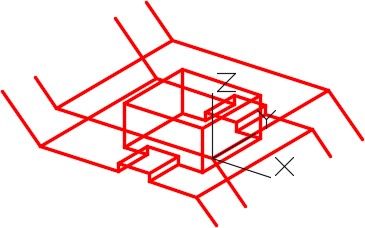
Freeze layer: Construction. Change the current UCS to World and the current view to SE Isometric. (Figure Step 17)
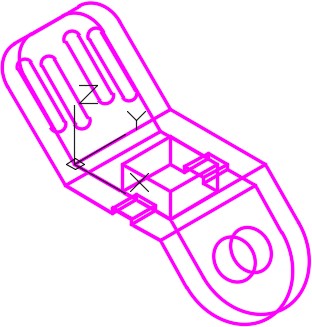
Step 18
Enter the UNITS command. In the Units dialogue box, set the Insertion Units to Millimeters. Insert the key: AutoCAD 3D Workalong 05-2. It will overlay the model with a magenta model. If it overlays your model perfectly, your model is accurately drawn. (Figure Step 18)
Step 19
Save and close the drawing.
MUST KNOW: The 3 Point icon is the easiest method of changing the UCS to lay on a plane. The order of selecting the 3 points is important. The order is as follows:
- The X0Y0Z0 or origin of the UCS.
- The direction of the positive X axis.
- The direction of the positive Y axis.
Ensure that you enable object snap to snap to existing objects to locate the UCS correctly.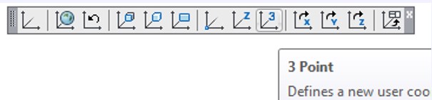
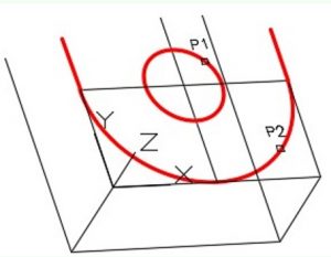
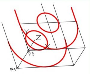
USER TIP: If you have to copy existing geometry in the Z direction, an easy way to do it is to use the COPY command and select the objects first (P1 and P2 – Step 1).
To indicate the copy distance and direction, snap to the ends of an existing line (P3 and P4 in Step 2).
Key Principles
Key Principles in Module 5
- Use the 3 Point method of orientating the UCS as much as possible. It is a very easy to use and will speed your model drawing time. The order of selecting the points is important. Pick 1 – The origin or X0Y0Z0, Pick 2 – The positive X Axis, Pick 3 – The positive Y axis.
- Before you start drawing any model, you must first decide what is the best view to start drawing first. Usually it is view with the most complex contour. This is called the Base view.
- The first view of a 3D wireframe model can be drawn in a 2D view. As soon as the objects are copied to make it three dimensional, the view must be changed to a 3D view before continuing the model construction.
Lab Exercise 5-1
Time allowed: 60 minutes.
| Drawing Name | Template | Units |
|---|---|---|
| AutoCAD 3D Lab 05-1 | 3D Layout English | Millimeters |
Step 1
Save and name the drawing: AutoCAD 3D Lab 05-1.
Step 2
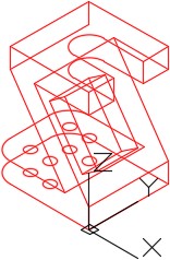
Draw a wireframe model of the object shown in the figure. (Figure Step 2A ,2B, 2C, 2D, 2E, 2F, and 2G)
Dimensioned Wireframe Model SE Isometric View
Step 3
Draw all construction objects on layer: Construction and all model objects on layer: Model.
Step 4
Start your model with the current view SE Isometric. If required, orbit it slightly with 3DFORBIT to help your line of sight.
Step 5
When complete, freeze layer: Construction.
Step 6
Enter the UNITS command. In the Units dialogue box, set the Insertion Units to Millimeters.
Step 7
Change the current UCS to World and check the model with the key.
Hint 1
See the steps below to draw the Front view.

Lab Exercise 5-2
Time allowed: 40 minutes.
| Drawing Name | Template | Units |
|---|---|---|
| AutoCAD 3D Lab 05-2 | 3D Layout Metric | Millimeters |
Step 1
Save and name the drawing: AutoCAD 3D Lab 05-2.
Step 2
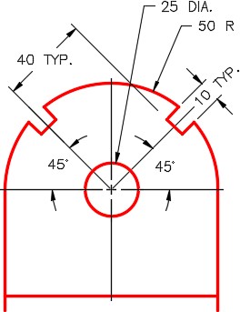
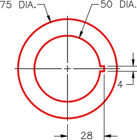
Draw a wireframe model of the object shown in the figure. (Figure Step 2A, 2B, 2C, 2D, and 2E)
Dimensioned Wireframe Model SE Isometric View
Step 3
Draw all construction objects on layer: Construction and all model objects on layer: Model.
Step 4
Start your model with the current view SE Isometric. If required, orbit it slightly with 3DFORBIT to help your line of sight.
Step 5
When complete, freeze layer: Construction.
Step 6
Enter the UNITS command. In the Units dialogue box, set the Insertion Units to Millimeters.
Step 7
Change the current UCS to World and check the model with the key.
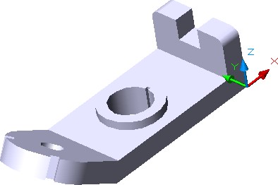
Completed Wireframe Model SE Isometric View
Completed Wireframe Model Orbited View
Completed Wireframe Model Orbited View
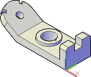
Solid Model – SE Isometric View
Lab Exercise 5-3
Time allowed: 60 minutes.
| Drawing Name | Template | Units |
|---|---|---|
| AutoCAD 3D Lab 05-3 | 3D Layout English | Inches |
Step 1
Save and name the drawing: AutoCAD 3D Lab 05-3.
Step 2
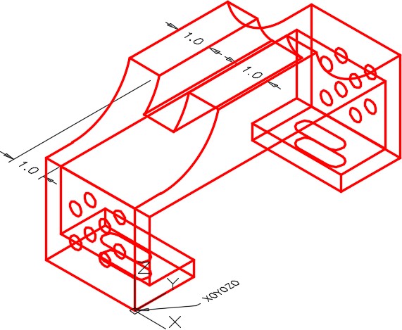
Draw a wireframe model of the object shown in the figure. (Figure Step 2A, 2B, 2C, 2D, 2E, 2F, and 2G)
Dimensioned Wireframe Model SE Isometric View
Step 3
Draw all construction objects on layer: Construction and all model objects on layer: Model.
Step 4
Start your model with the current view SE Isometric. If required, orbit it slightly with 3DFORBIT to help the line of sight.
Step 5
When complete, freeze layer: Construction.
Step 6
Enter the UNITS command. In the Units dialogue box, set the Insertion Units to Inches.
Step 7
Change the current UCS to World and check the model with the key.
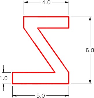
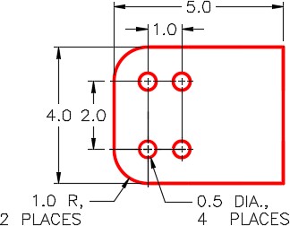
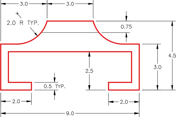
Front View
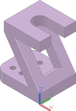
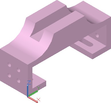
Solid Model – SE Isometric View
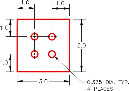
Detail of Top
Detail of Bottom
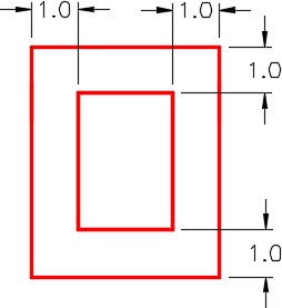
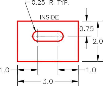
Detail of Square Hole in Inclined
Hint 1
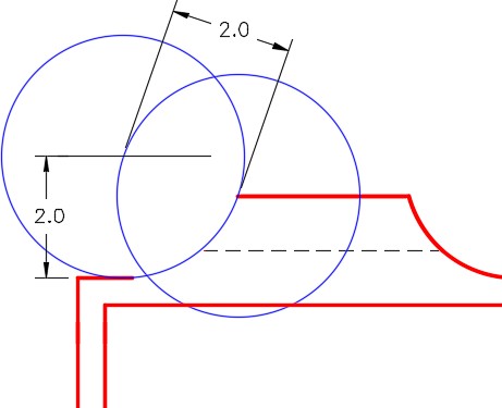
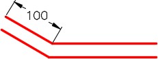
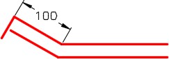
To draw the inclined line, see the steps below. (Figure Hint 1)
Step 1
Draw a construction line from corner to corner and a 1 diameter construction circle with the centre at the midpoint of the line.
Step 2
Draw two lines from the endpoints tangent to the circle.
Step 3
Extend the lines and trim the horizontal lines.
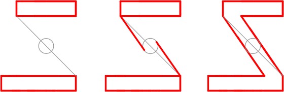
Step 1 Step 2 Step 3
Lab Exercise 5-4
Time allowed: 60 minutes.
| Drawing Name | Template | Units |
|---|---|---|
| AutoCAD 3D Lab 05-4 | 3D Layout English | Inches |
Dimensioned Wireframe Model SE Isometric View
Step 1
Save and name the drawing: AutoCAD 3D Lab 05-4.
Step 2
Draw a wireframe model of the object. (Figure Step 2A, 2B, 2C, 2D, 2E, and 2F)
Step 3
Draw all construction objects on layer: Construction and all model objects on layer: Model.
Step 4
Start your model with the current view SE Isometric. If required, orbit it slightly with 3DFORBIT to help your line of sight.
Step 5
When complete, freeze layer: Construction.
Step 6
Enter the UNITS command. In the Units dialogue box, set the Insertion Units to Inches.
Step 7
Change the current UCS to World and check the model with the key.
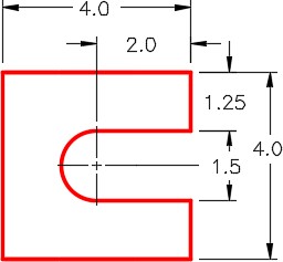
Right Side View
Front and Back Detail TYP.
Bottom Detail TYP.
Solid Model – SE Isometric View
SE Isometric View
Hint 1
To draw the arc, you must draw the construction circle and lines to locate its centre. (Figure Hint 1)